RS-1_instruction manual.pdf - 第947页
Part 2 D etaile d Descript ion of E ach Functi on Chapter 12 Handling th e Optional Device s 12 - 63 Y ou can cont inue teach ing, and use the autom atic adjustment funct i on on the “ Set Solder Recogniti on Paramet er …
Part 2 Detailed Description of Each Function Chapter 12 Handling the Optional Devices
12-62
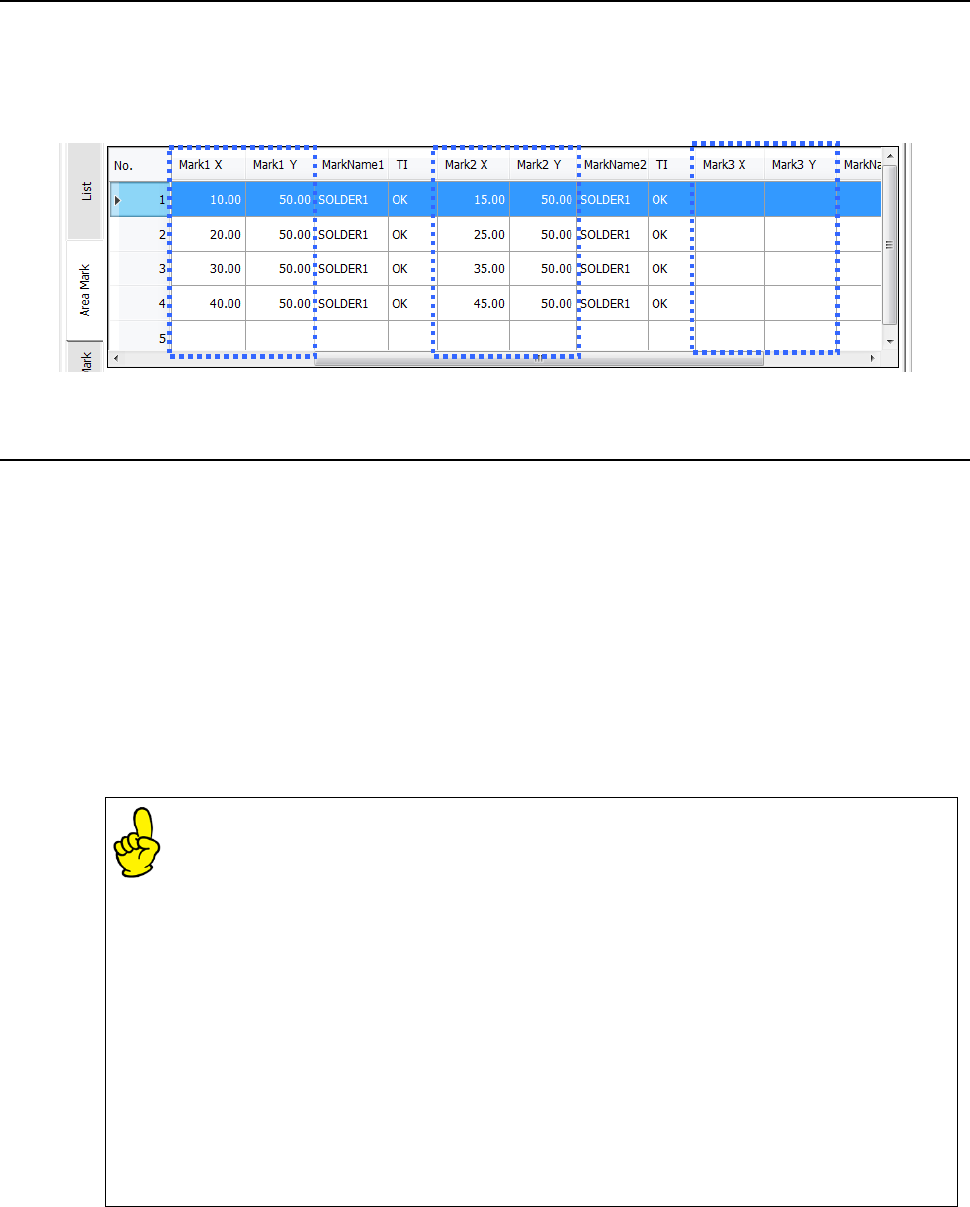
12.11.7.2 Entering a mark coordinate
Enter coordinates of two or three component placement positions to recognize solder in the “Mark X”
and “Mark Y” columns when you select [Solder] as the “Mark Type.”
However, when you select [Solder (PWB)] as the “Mark Type,” you can enter a coordinate value in
the reference circuit coordinate system even though it is outside the reference circuit.
12.11.7.3 Teaching
Adjust the cursor to the [TI] position and press the [Teaching] button in the operation area. Then,
execute solder teaching.
* The brightness of positions to be taught may vary because solder is used. Therefore, perform
not the Vision Copy function but the mark teaching operation.
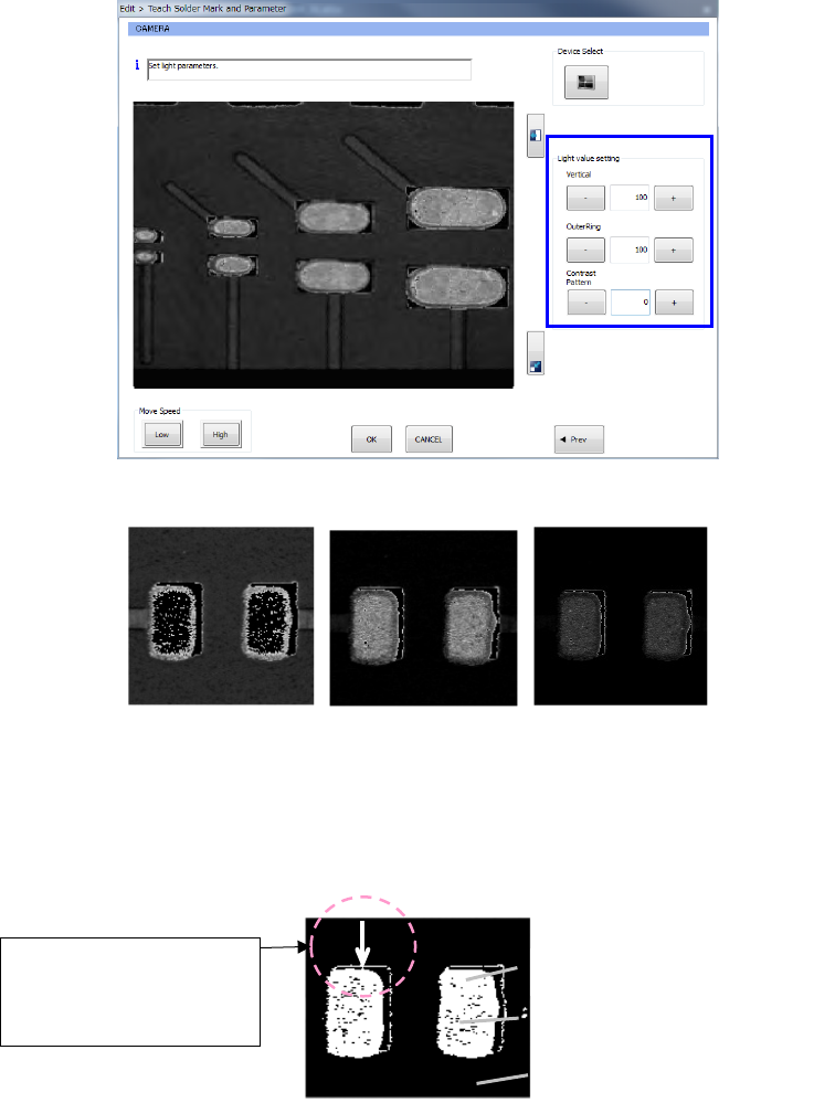
(1) Light adjustment
While checking the VCS monitor, adjust each parameter: [Vertical Light], [Solder Light] and
[Contrast Pattern] so that the contrast between the screen-printed solder and a board can be
good.
Enter the desired value into the edit box directly or select the arrow mark located on the right
side of the edit box to change each parameter.
The setting of the [Vertical Light] mainly affects the brightness of a pad or resist section
of a board, and the setting of the [Solder Light] mainly affects the brightness of solder.
* When the system recognizes screen-printed solder, it converts the luminance of the
portion whose luminance is high such as an electrode pattern of a board to “0.”
Therefore, the system adjusts the parameters of the [Vertical Light] item and the
[Solder Light] item so that the luminance of the electrode pad section can look
highest, that of solder can look moderate, and that of other portions can look dark.
* If there are black spots (whose luminance is “0”) on the screen-printed solder due to
roughness of the surface of the screen-printed solder when the system adjusts a
binary threshold or recognizes the solder, set the luminance of the light so that it can
be darker than the set luminance.
* The setting of the [Contrast Pattern] item is a parameter that changes the sensitivity
of a camera. If the recognition condition cannot be improved by adjustment of the
lights, it allows the system to select the number that makes the contrast between the
screen-printed solder and the board good.
Part 2 Detailed Description of Each Function Chapter 12 Handling the Optional Devices
12-63
You can continue teaching, and use the automatic adjustment function on the “Set Solder
Recognition Parameter” screen in order to set the parameters automatically.
After adjustment, select the <OK> button. The system updates the adjustment value and
goes to the next process.
When you select the <APPLY> button, the adjustment value is updated. When you select
the <CANCEL> button, the system stops teaching.
- Example of recognition images (Left: Too bright, Center: Good, Right: Too dark)
(2) Setting a binary threshold value
Use the upper and/or lower arrow key to adjust a binary threshold value so that only solder
displayed on the monitor can look bright.
Like the outline of the electrode pad displayed in the Figure 12.12.8.6, any gloss of about one
pixel other than solder will not affect recognition of solder.
You can continue teaching, and use the automatic adjustment function on the “Set Solder
Recognition Parameter” screen to set a parameter automatically also.
If you cannot adjust the threshold value easily, use the PERVIOUS key to return to the light
adjustment screen and readjust the light.
Solder
Electrode pad
Resist section of a board
If the thickness of the
outline is about one pixel,
it will not affect
recognition of solder.
Part 2 Detailed Description of Each Function Chapter 12 Handling the Optional Devices
12-64
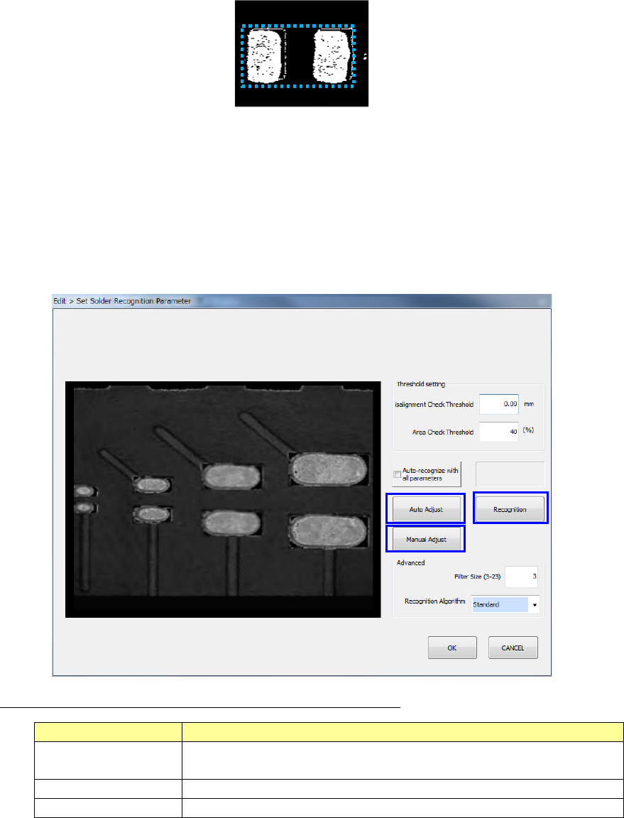
(3) Setting the solder shape
Specify two upper left and lower right points of the window so that it can come in contact with
a pair of screen-printed solders by operating the screen, and select the [OK] key.
(4) Setting a misalignment check threshold value
Enter a misalignment check threshold value to be detected by the solder position
misalignment check and the area ratio threshold value to be detected by the condition check.
The detection area is to be “the solder dimensions to be obtained during teaching” + “the
misalignment check threshold value.” When you select the <OK> button, the system
updates the threshold values and proceeds to the next process.
* The system sets the detection area based on the “Misalignment Check Threshold” value.
* When you enter “0” into the “Area Check Threshold” field, the system will not check the
area ratio.
Description of the command buttons displayed on the screen
Button name
Description
Auto Adjust This button automatically adjusts the lights, the threshold values and
the contrast pattern.
Recognized Result
This button recognizes a solder mark.
Manual adjustment
Moves to the manual adjustment screen.
<Operation with a keyboard>
1. Use the [Tab] key to move the focus into the edit box.
2. Enter the desired value into the edit box.
3. Use the [Tab] key to move the focus into the corresponding command button, and then
press the Enter key.
①
③
②