User Manual SIPLACE Head Care Station -.pdf - 第24页
2 Safety 2.7 Safety features 24 User Manual SIPLACE Head Care Station 10/2017 2.7.2.2 Description of functions Main power switch in ON position (see item (1) in 2.7.2.1 "Position of switches and buttons on the HCS&q…
2 Safety
2.7 Safety features
User Manual SIPLACE Head Care Station 10/2017 23
2.7.2 Switches and buttons on the HCS
2.7.2.1 Position of switches and buttons on the HCS
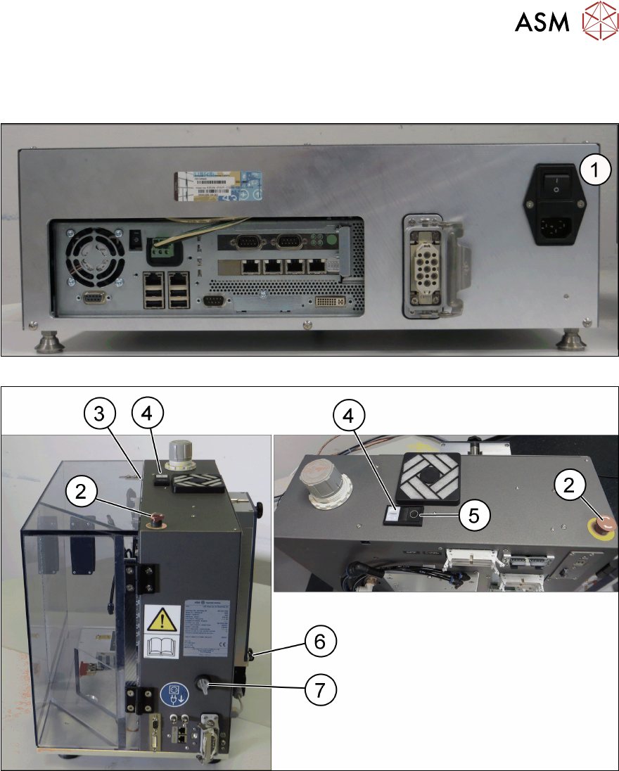
Fig.14: Control box – back side
Fig.15: Head unit - right side / top view
1 Main power switch on control box 2 EMERGENCY OFF button
3 Safety switch of door [03158868-xx] 4 Start button
5 Stop button 6 Safety switch of cover [03159513-xx]
7 HCS power switch

2 Safety
2.7 Safety features
24 User Manual SIPLACE Head Care Station 10/2017
2.7.2.2 Description of functions
Main power switch in ON position
(see item (1) in 2.7.2.1 "Position of switches and buttons on the HCS" [}23])
Switching on the main power switch provides the control box with 24VDC and 42VDC.
Main power switch in OFF position
Switching off the main power switch disconnects the complete HCS from the power supply.
DANGER
Death, serious injury or considerable damage may result if the HCS is handled incor-
rectly
► Always follow the applicable accident prevention and safety regulations (particularly
DIN EN 60204, part 1 or IEC 60204, part 1) and the safety regulations in your own
country.
HCS power switch
(see item (7) in 2.7.2.1 "Position of switches and buttons on the HCS" [}23])
Switching on the HCS power switch provides current to the head via the control box.
Switching off the HCS power switch disconnects the head from the power supply.
Start button
(see item (4) in 2.7.2.1 "Position of switches and buttons on the HCS" [}23])
The Start button performs the following tasks:
●
Initializes the head unit and the installed placement head.
●
After initializing the head, pressing the Start button again locks the door.
●
Resumes the head verification process after it was stopped.
NOTICE
Start button not active
The Start button does not work if the HCS power switch is still in the OFF position or if the
flat ribbon cables are not connected correctly.
Stop button
(see item (5) in 2.7.2.1 "Position of switches and buttons on the HCS" [}23])
The Stop button performs the following tasks:
●
Unlocks the door before a head verification process has been started
In the middle of a running head verification process, however, the Stop button neither unlocks the
door nor stops the verification process.
If a stop is required during the head verification process, you have the following options:
●
Press the EMERGENCY OFF button in case of an emergency.
●
Click the Cancel button in the software. See item (6) in 5.2.6.5 "Measurement pro-
gress" [}70].
●
Click the Stop button in the software. See item (5) in 5.2.6.5 "Measurement progress" [}70].

2 Safety
2.7 Safety features
User Manual SIPLACE Head Care Station 10/2017 25
EMERGENCY OFF button
(see item (2) in 2.7.2.1 "Position of switches and buttons on the HCS" [}23])
The EMERGENCY OFF button is red and latches in the ON position when pressed. When you
press the EMERGENCY OFF button, the safety contactor trips. The intermediate circuit voltage
(150VDC) for the star axes is switched off. The message "EMERGENCY OFF pressed" appears
on the screen. The servo amplifiers for the DP and Z axes are still supplied with 42VDC.
Press the EMERGENCY OFF button in case of an emergency. It performs the following tasks:
●
Stops the power supply of 150V to the head unit.
●
Puts the HCS in idle mode.
●
Aborts the current test run of the head verification process.
●
Unlocks the door.
NOTICE
The verification process is interrupted and can then either be continued or cancelled once
the HCS is working correctly again.
Continuing the head verification process
If the EMERGENCY OFF button has been pressed during a running test, the test is aborted.
► Ensure that head and stopper are installed correctly.
► Close the door.
► Release the EMERGENCY OFF button from the latched position.
► Switch on the HCS power switch.
► Press the Start button on the head unit.
ð The verification process is resumed. The aborted test is repeated and the process is con-
tinued from there.
Safety switch, protective door
This switch checks whether the protective door is open or closed. When the door is opened, the
safety switch triggers the safety contactor disabling individual components while some remain en-
abled.
Safety switch, cover
This switch checks whether the cover is open or closed. When the cover is opened, the safety
switch triggers the safety contactor disabling individual components while some remain enabled.
2.7.3 Safety contactor
The safety contactor is located in the head unit. It is used for the interlock function of the safety
equipment and for the EMERGENCY OFF function.
The following conditions must be fulfilled in order to activate the safety contactor:
●
All safety components must be closed.
●
The EMERGENCY OFF button must be released.
●
To start the verification process, the Start button must have been pressed, or to restart a
measurement, the Continue button must have been clicked.
As a result, the software activates locking of the door. When the door is locked, the safety con-
tactor is enabled.