User Manual SIPLACE Head Care Station -.pdf - 第35页
3 HCS description 3.1 Overview of the modules User Manual SIPLACE Head Care Station 10/2017 35 3.1.1.1 Tool area Fig.22: Tool area without tool Fig.23: Tool area with tool inserted 1 Stopper CP20 - CPP HCSII [03095249-…
3 HCS description
3.1 Overview of the modules
34 User Manual SIPLACE Head Care Station 10/2017
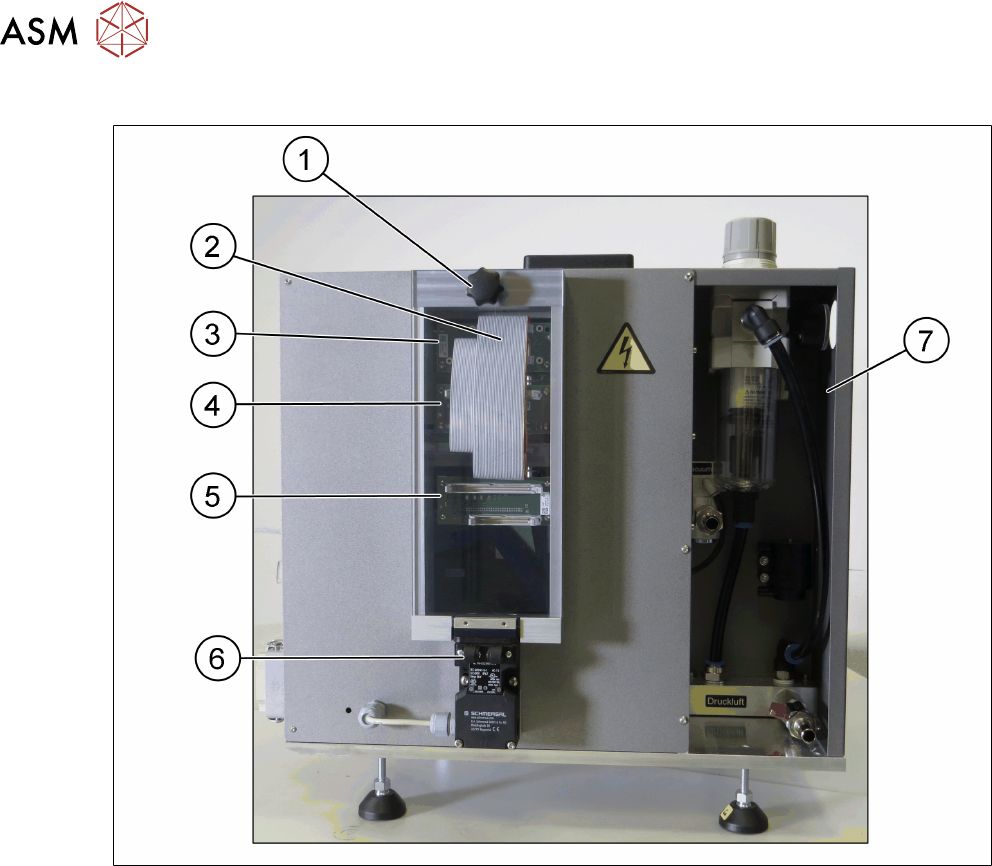
Head unit – Back side view
Fig.21: Head unit – back side view
1 Cover [03089224-xx] with knob 2 Flat ribbon cables
3 Board Adapter-LP C700B-HCSII
[03087842-xx]
4 Board Adapter-LP CPP/CP20-HC-
SII[03087843-xx]
5 Board Adapter-LP DLM4/TWIN-HC-
SII[03087844-xx]
6 Safety switch for cover [03159513-xx]
7 Pneumatic unit [03079075-xx]
3 HCS description
3.1 Overview of the modules
User Manual SIPLACE Head Care Station 10/2017 35
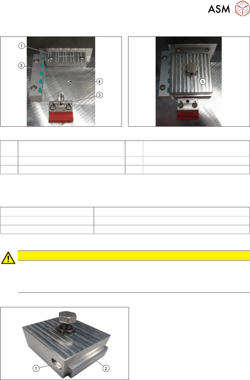
3.1.1.1 Tool area
Fig.22: Tool area without tool Fig.23: Tool area with tool inserted
1 Stopper CP20 - CPP HCSII
[03095249-xx]
2 End stop with sensors for tool identifica-
tion [03085732-xx]
3 Tool clamping [03146437-xx] 4 Place where to insert the tool
5 Inserted tool
Stopper
The stopper aligns the tools to the Z-axis of the head to be verified.
Two stoppers are available and to be used for the respective placement heads:
Stopper Placement head
CP20 – CPP HCSII [03095249-xx] C&P20A, C&P20P, C&P20M, C&P20M2, CPP, CPPM
P+P HCSII [03119655-xx] P&P module
Wrong stopper
CAUTION
Wrong stopper!
A stopper that is not intended for the currently installed placement head could lead to wrong
measurement results during head verification.
► Always ensure to install the correct stopper.
Verification tool
Fig.24: Unit for endurance test HCSII [03086515-xx]
1 Recess for tool identification 2 Edge to mark tool front
For the individual tests of a head verification process, different tools are required.
3 HCS description
3.1 Overview of the modules
36 User Manual SIPLACE Head Care Station 10/2017
During head verification, the software tells you which tool to insert before the next step. Each test
starts with the endurance test unit.
To make sure that the orientation of the inserted tool is correct, each tool has a distinct edge(1) at
the front to identify the tool front. The tool is correctly positioned in the tool area if its front points to-
wards you.
Each tool has a unique recess(1) on its left side for identification purposes. If the sensors in the
sensor bar cannot identify the inserted tool as the correct tool, a warning message is displayed on
the screen.
CAUTION
Tool not correctly aligned!
If the tool is not inserted correctly, damage to the mounted placement head could occur
during head verification. This could also lead to wrong measurement results.
► Always ensure to insert and clamp the tool correctly.
3.1.2 Control box
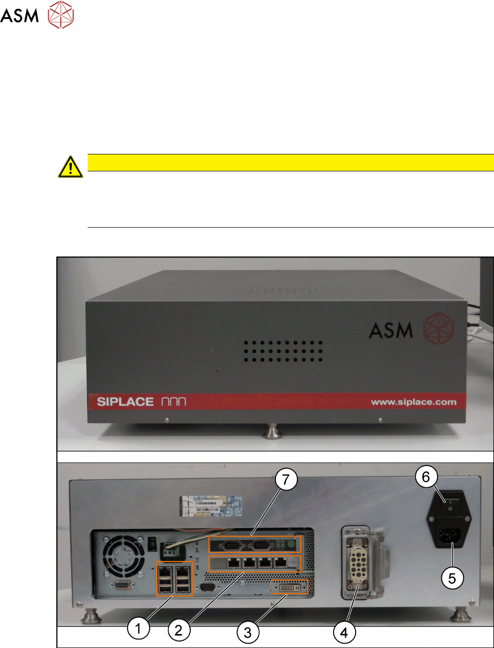
Fig.25: Control box [03149138-xx]
1 USB and LAN connector 2 Hotlink connector
3 DVI connection for monitor 4 Connector power supply to the head unit
5 Connector for main power supply 6 Main power switch incl. micro fuse 4.0A
(5x20 Time-Lag 250VAC ceramic)
7 CAN-Bus connector