User Manual SIPLACE Head Care Station -.pdf - 第39页
3 HCS description 3.1 Overview of the modules User Manual SIPLACE Head Care Station 10/2017 39 3.1.5 Option vacuum pump HCS II [03107491-xx] NOTICE Vacuum pump operation The HCS is prepared for both compressed air (Ventu…
3 HCS description
3.1 Overview of the modules
38 User Manual SIPLACE Head Care Station 10/2017
3.1.4 Case with tools [03122285-xx]
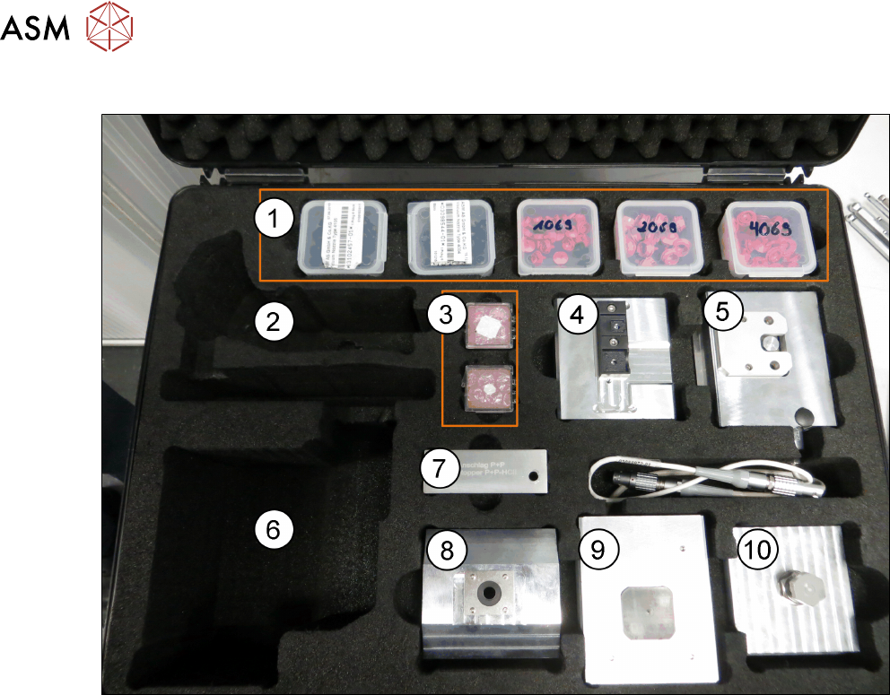
Fig.27: Case with tools
1 5x Plastic case 36x36x12 [00384333-xx]
with:
●
Nozzle type 2069 cpl. [03094135-xx]
●
Nozzle type 1069 [03094112-xx]
●
Nozzle type 4069 [03106244-xx]
●
Nozzle type 4004 [03098544-xx]
●
Nozzle type 4105 [03102457-xx]
2 Space for component camera SST23
[03003426Sxx]
3 Calibration jig version SST23
[03034148-xx]
Calibration part version 3 [03010565-xx]
4 Calibration tool pocket [03086419-xx]
5 Force-measurement-unit – HCSII
[03086502-xx]
6 Space for component camera SST30
[03085394Sxx]
7 Stopper P+P – HCSII [03119655-xx] 8 Nozzle station CP20-HCSII
[03086323-xx]
9 Vacuum-pressure measurement unit –
HCSII [03085726-xx]
10 Unit for endurance test HCSII
[03086515-xx]
3 HCS description
3.1 Overview of the modules
User Manual SIPLACE Head Care Station 10/2017 39
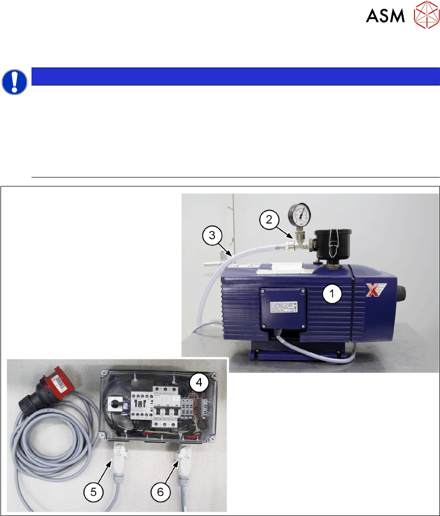
3.1.5 Option vacuum pump HCS II [03107491-xx]
NOTICE
Vacuum pump operation
The HCS is prepared for both compressed air (Venturi) and vacuum pump operation.
The only vacuum pump tested and released up to now is the pump known from the X-
SeriesS machines. To eliminate unwanted effects regarding the pump performance and
the flow capacity, and to ensure a proper head verification, only use the released vacuum
pump.
For more information, see the HCS vacuum pump assembly instructions [00198017-xx].
Fig.28: HCS vacuum pump and accessories
1 Vacuum pump Becker VX4 25
[03069679-xx]
2 Vacuum pump connection, manometer
and filter unit
3 Spiral coiled tube for vacuum pump HC-
SII [03120432-xx]
4 Vacuum pump connection unit HCSII
cpl. [03120295-xx]
5 Cable: Power connection under vacuum
pump HCS [03122252-xx]
6 Cable: Power vacuum pump HCS
[03122253-xx]
3 HCS description
3.1 Overview of the modules
32 User Manual SIPLACE Head Care Station 10/2017
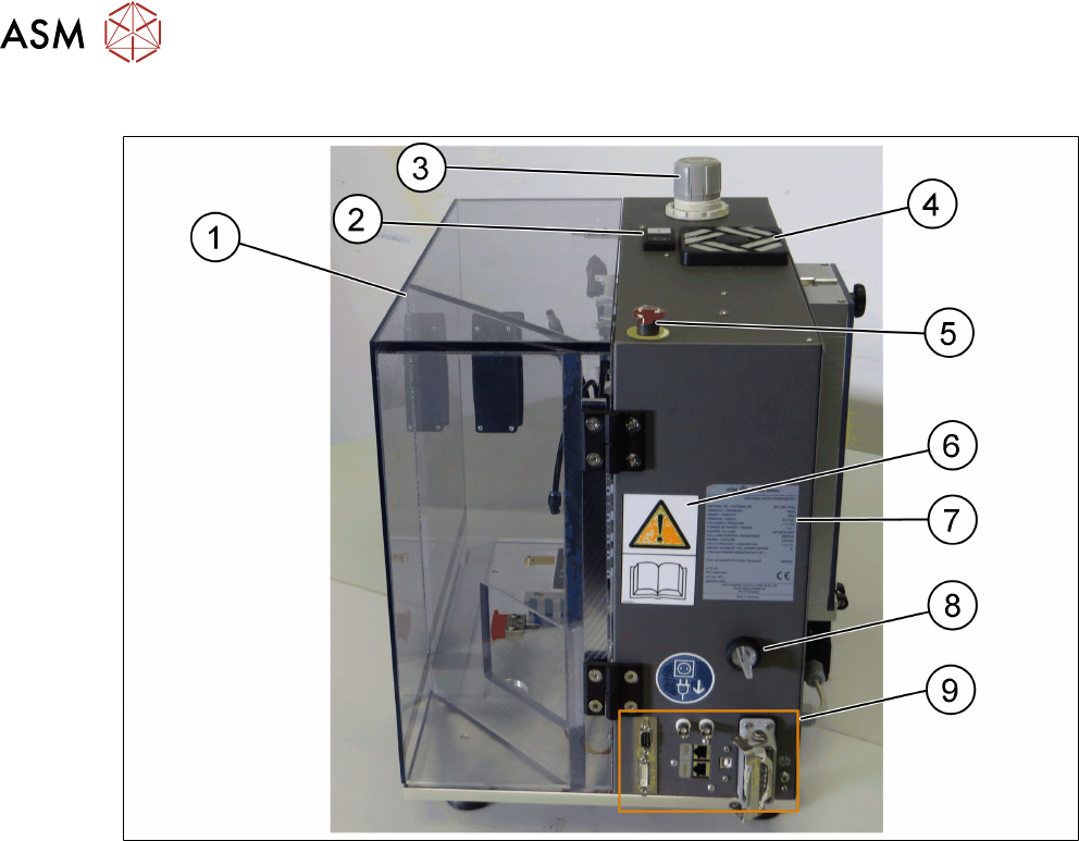
Head unit – Right side view
Fig.18: Head unit – right side view
1 Door [03156199-xx] 2 Start/Stop button [00349458-xx]
3 Wheel for compressed air adjustment
[03079075-xx]
4 Filter unit [03003425-xx]
5 EMERGENCY OFF button
[03062334-xx]
6 W 201 [03009338-xx]
7 Type plate Head Care Station V2.3
[03158942-xx]
8 HCS power switch [03099566-xx]
9 Interfaces for cable connections