User Manual SIPLACE Head Care Station -.pdf - 第42页
3 HCS description 3.2 Technical data 42 User Manual SIPLACE Head Care Station 10/2017 3.2 Technical data 3.2.1 Placement heads supported ● SIPLACE SpeedStar (C&P20, C&P20A+M, C&P20P+M2) ● SIPLACE MultiStar …
3 HCS description
3.1 Overview of the modules
User Manual SIPLACE Head Care Station 10/2017 41
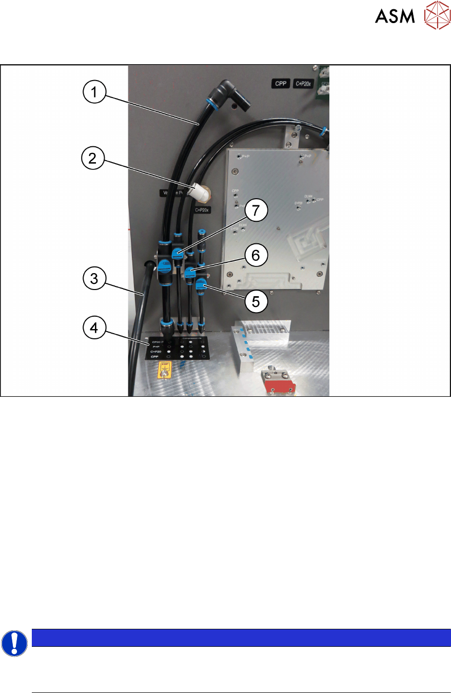
3.1.6.2 Pneumatic connections for the heads
Fig.30: Pneumatic connections for the heads
1 Compressed air supply [03121180-xx]
with valve [03098515-xx] to all C&P20x
heads
2 Vacuum supply to all C&P20x heads
3 Exhaust line for all heads [03121180-xx] 4 Label [03092199-xx] showing which
hoses to be used for each type of head
5 Compressed air supply [03121180-xx]
with valve [03039632-xx] for the return
unit P&P module.
6 Compressed air supply [03121180-xx]
with valve [03039632-xx] for
●
PRV of all C&P20x heads
●
CPP head valve
7 Compressed air supply [03121180-xx]
with valve [03039632-xx] to PRV of
●
CPP
●
P&P module
NOTICE
Obey the label!
The label indicates which hoses are to be used for the mounted placement head.
► Obey the label(5) when mounting the heads.

3 HCS description
3.2 Technical data
42 User Manual SIPLACE Head Care Station 10/2017
3.2 Technical data
3.2.1 Placement heads supported
●
SIPLACE SpeedStar (C&P20, C&P20A+M, C&P20P+M2)
●
SIPLACE MultiStar (CPP)
●
SIPLACE TwinStar (TH)
See also
2 1.1.5 "Failure to use as prescribed" [}9]
3.2.2 Functional range
Depending on the head type, the functional range can slightly differ:
●
Condition of the vacuum system and its sub-units
●
Movement of DP- and Z-axis bearings
●
Wear on bearings / tolerances
●
Check of the component sensor
●
Check of the z-axis light barrier
●
Check of the nozzle seating
●
Position accuracy of DP drives
●
Placement force verification
3.2.3 Ambient conditions and connection values
3.2.3.1 Ambient conditions for packaging, transportation and storage
●
Temperature range between -25°C and 55°C
●
Atmospheric humidity up to 95%
●
Ambient pressure up to 1700m height without pressure equalization
3.2.3.2 Ambient conditions for machine operation
●
Room temperature between 15°C and 35°C
●
Atmospheric humidity of 30% to 75%
●
To avoid any possibility of condensation on the machine, make sure that the average atmo-
spheric humidity is no higher than 45%.
●
Ambient pressure > 750mbar (corresponds to 2500m above mean sea level)
4 Setting up and commissioning
4.2 Setting up the HCS
48 User Manual SIPLACE Head Care Station 10/2017
4.2.2 Pneumatic connections
► Connect the vacuum pump or compressed air supply to the pneumatic unit as shown in the
following picture:
Fig.34: Pneumatic unit
1 Spiral coiled tube for vacuum pump con-
nection
2 Main valve for compressed air supply
3 1/2" tube for compressed air generator
connection
NOTICE
Input valves not closed
Ensure the input valves are closed when connecting either the compressed air supply or the va-
cuum pump.
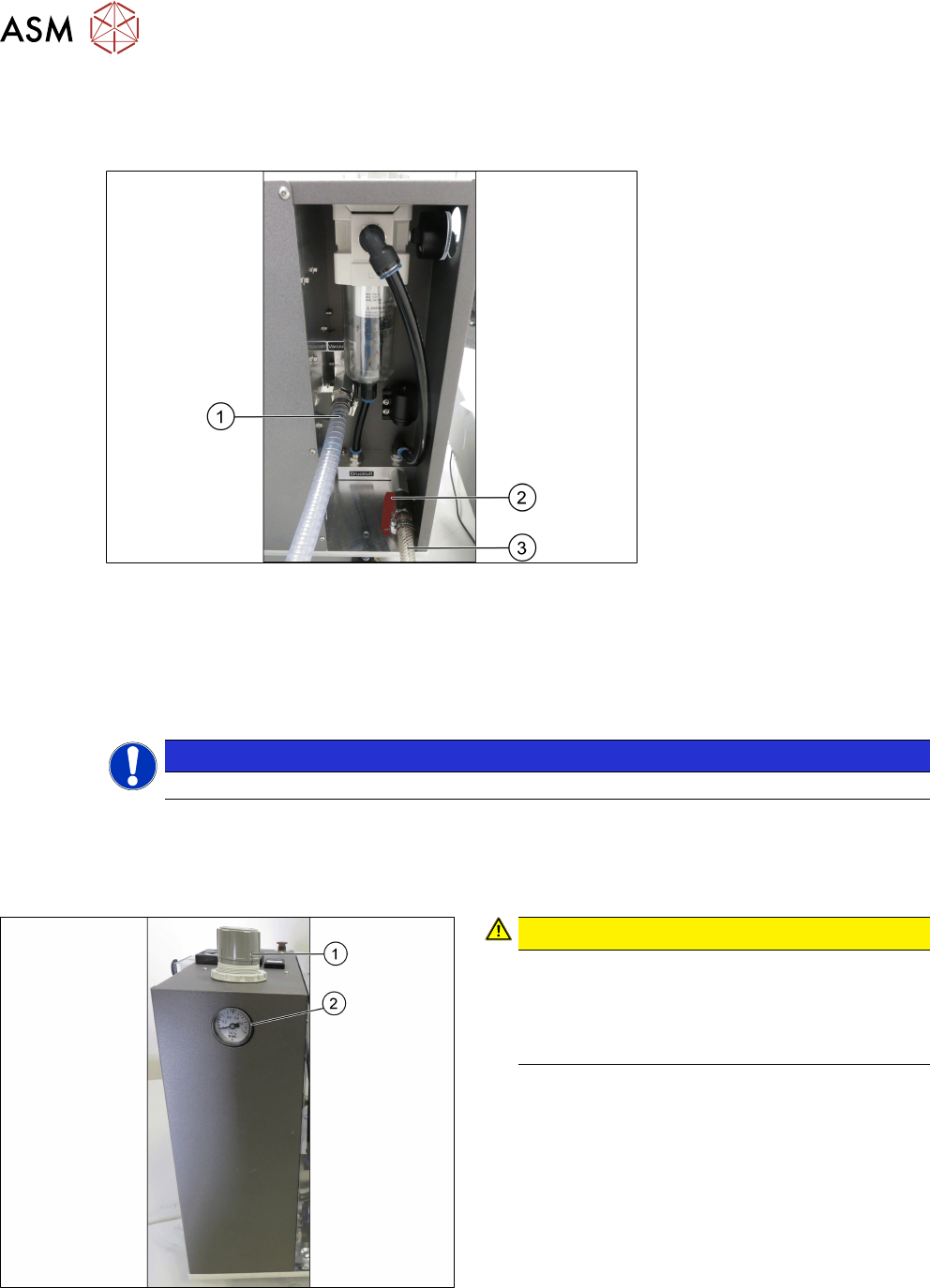
4.2.3 Adjusting the pneumatic supply
Fig.35: Adjustment wheel and manometer
CAUTION!
Risk of injury due to loose pneumatic hoses!
Always ensure that the valves of the pneu-
matic connections for the heads are closed
before opening the main valve for com-
pressed air.
.
► Ensure that all valves of the pneumatic connec-
tions for the heads are closed.
► Open the main valve of the compressed air sup-
ply.
► Pull off the cap(1) of the adjustment wheel.
► Turn the adjustment wheel until the mano-
meter(2) shows 4.8 bar.
► Push down the cap(1) of the adjustment wheel to
secure the setting.
► Close the main valve of the compressed air sup-
ply.