User Manual SIPLACE Head Care Station -.pdf - 第44页
4 Setting up and commissioning 4.3 Software HCS 52 User Manual SIPLACE Head Care Station 10/2017
4 Setting up and commissioning
4.2 Setting up the HCS
48 User Manual SIPLACE Head Care Station 10/2017
4.2.2 Pneumatic connections
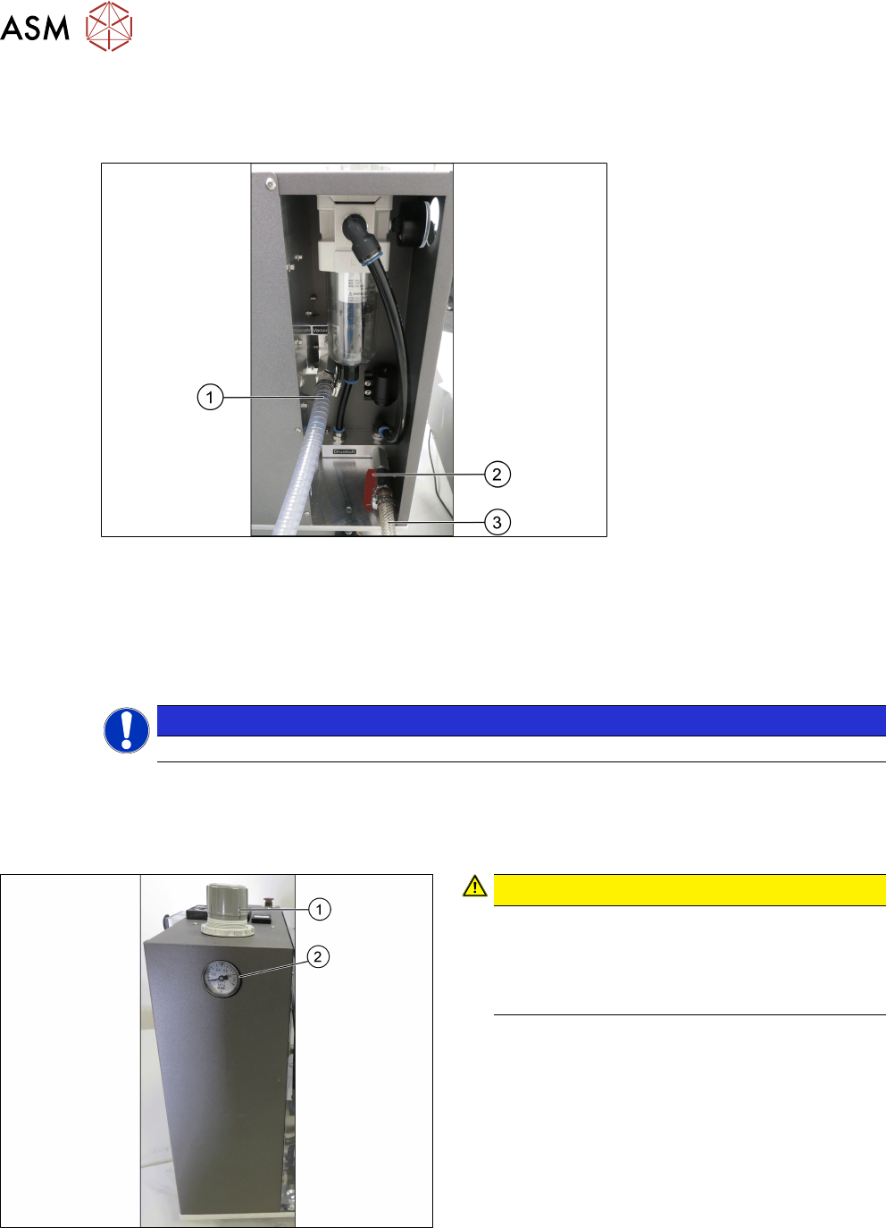
► Connect the vacuum pump or compressed air supply to the pneumatic unit as shown in the
following picture:
Fig.34: Pneumatic unit
1 Spiral coiled tube for vacuum pump con-
nection
2 Main valve for compressed air supply
3 1/2" tube for compressed air generator
connection
NOTICE
Input valves not closed
Ensure the input valves are closed when connecting either the compressed air supply or the va-
cuum pump.
4.2.3 Adjusting the pneumatic supply
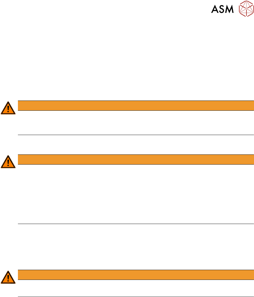
Fig.35: Adjustment wheel and manometer
CAUTION!
Risk of injury due to loose pneumatic hoses!
Always ensure that the valves of the pneu-
matic connections for the heads are closed
before opening the main valve for com-
pressed air.
.
► Ensure that all valves of the pneumatic connec-
tions for the heads are closed.
► Open the main valve of the compressed air sup-
ply.
► Pull off the cap(1) of the adjustment wheel.
► Turn the adjustment wheel until the mano-
meter(2) shows 4.8 bar.
► Push down the cap(1) of the adjustment wheel to
secure the setting.
► Close the main valve of the compressed air sup-
ply.

4 Setting up and commissioning
4.3 Software HCS
52 User Manual SIPLACE Head Care Station 10/2017
4 Setting up and commissioning
4.1 Infrastructure at the installation location
User Manual SIPLACE Head Care Station 10/2017 45
4 Setting up and commissioning
4.1 Infrastructure at the installation location
4.1.1 Recommendations for foundation quality
The foundation on which the HCS is to be placed must be firm and levelled. Make sure the HCS is
placed evenly on the foundation (no tilt). It is recommended to use a stable table or bench as
foundation and adjust its height properly so that the HCS can easily be reached by the operator.
WARNING
Risk of injury due to heavy parts!
► Never set up the HCS head unit alone. Make sure that at least one other person helps
with setting up the HCS head unit.
4.1.2 Main power supply
WARNING
Some parts of the system carry potentially lethal voltages
The machine is supplied with 1/N/PE 100V~ to 240V~, 50/60Hz mains voltage. This
means that some parts of the system carry potentially lethal voltages - even when switched
off at the main power switch. Incorrect handling of the head care station can therefore result
in death or severe injury or considerable damage to equipment.
► Always follow the applicable accident prevention and safety regulations (particularly
DIN EN 60204, part 1 or IEC 60204, part 1) and the safety regulations in your own
country.
4.1.2.1 Mains connection
The main power connection is configured according to the power supply of the country concerned.
●
The HCS is configured for 1/N/PE 100V~ to 240V~.
●
The HCS has a mains power cord with plug.
WARNING
Class I equipment!
For electrical safety, a protective earth connection is required.