User Manual SIPLACE Head Care Station -.pdf - 第45页
4 Setting up and commissioning 4.1 Infrastructure at the installation location User Manual SIPLACE Head Care Station 10/2017 45 4 Setting up and commissioning 4.1 Infrastructure at the installation location 4.1.1 Recomme…

4 Setting up and commissioning
4.3 Software HCS
52 User Manual SIPLACE Head Care Station 10/2017
4 Setting up and commissioning
4.1 Infrastructure at the installation location
User Manual SIPLACE Head Care Station 10/2017 45
4 Setting up and commissioning
4.1 Infrastructure at the installation location
4.1.1 Recommendations for foundation quality
The foundation on which the HCS is to be placed must be firm and levelled. Make sure the HCS is
placed evenly on the foundation (no tilt). It is recommended to use a stable table or bench as
foundation and adjust its height properly so that the HCS can easily be reached by the operator.
WARNING
Risk of injury due to heavy parts!
► Never set up the HCS head unit alone. Make sure that at least one other person helps
with setting up the HCS head unit.
4.1.2 Main power supply
WARNING
Some parts of the system carry potentially lethal voltages
The machine is supplied with 1/N/PE 100V~ to 240V~, 50/60Hz mains voltage. This
means that some parts of the system carry potentially lethal voltages - even when switched
off at the main power switch. Incorrect handling of the head care station can therefore result
in death or severe injury or considerable damage to equipment.
► Always follow the applicable accident prevention and safety regulations (particularly
DIN EN 60204, part 1 or IEC 60204, part 1) and the safety regulations in your own
country.
4.1.2.1 Mains connection
The main power connection is configured according to the power supply of the country concerned.
●
The HCS is configured for 1/N/PE 100V~ to 240V~.
●
The HCS has a mains power cord with plug.
WARNING
Class I equipment!
For electrical safety, a protective earth connection is required.
4 Setting up and commissioning
4.2 Setting up the HCS
46 User Manual SIPLACE Head Care Station 10/2017
4.2 Setting up the HCS
As all software packages which are required for head verification are pre-installed on the HCS by
default, the HCS is immediately ready for use.
4.2.1 Electrical connections
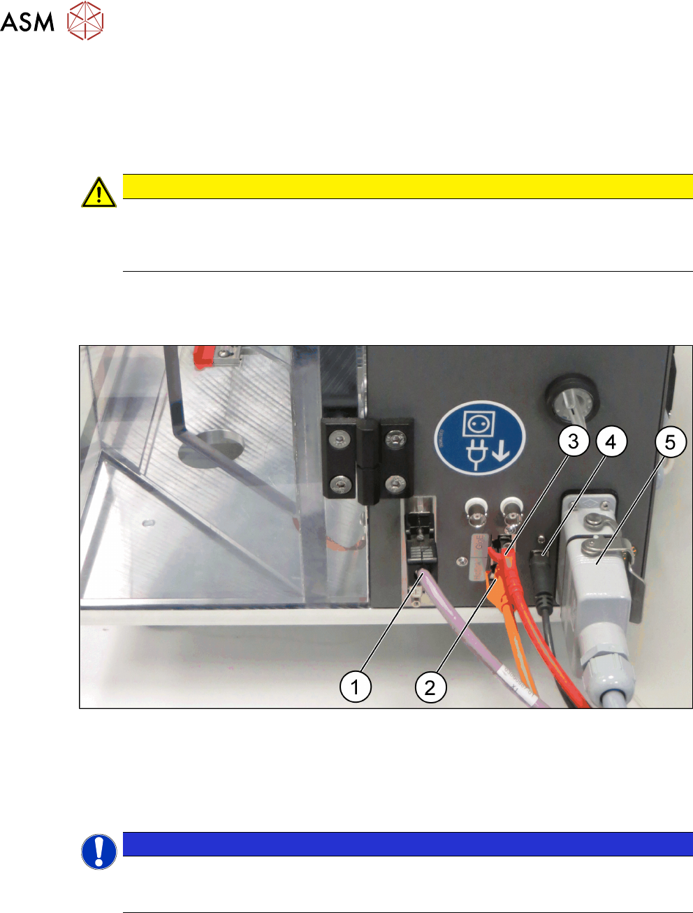
CAUTION
Risk of damaging the camera connections
Make sure to connect the camera cables in accordance with the used camera system. The
interchange of the hotlink with GigE or vice-versa can result in damage to the vision camera
interface.
Cable connections at the right side of the HCS head unit
► Connect the cables to the interface on the right side of the HCS head unit as shown in the fol-
lowing picture:
Fig.32: HCS head unit – right side view
1 CAN-Bus cable [03159108-xx] 2 Hotlink cable [03148066-xx]
3 GigE cable [03148067-xx] 4 USB cable [03148065-xx]
5 Connection cable HCS [03152929-xx]
NOTICE
GigE or Hotlink cable
Depending on the camera of the placement head, either connect the GigE cable or the hot-
link cable.