User Manual SIPLACE Head Care Station -.pdf - 第47页
4 Setting up and commissioning 4.2 Setting up the HCS User Manual SIPLACE Head Care Station 10/2017 47 Cable connections at the control box ► Connect the cables to the interfaces on the control box as shown in the follow…
4 Setting up and commissioning
4.2 Setting up the HCS
46 User Manual SIPLACE Head Care Station 10/2017
4.2 Setting up the HCS
As all software packages which are required for head verification are pre-installed on the HCS by
default, the HCS is immediately ready for use.
4.2.1 Electrical connections
CAUTION
Risk of damaging the camera connections
Make sure to connect the camera cables in accordance with the used camera system. The
interchange of the hotlink with GigE or vice-versa can result in damage to the vision camera
interface.
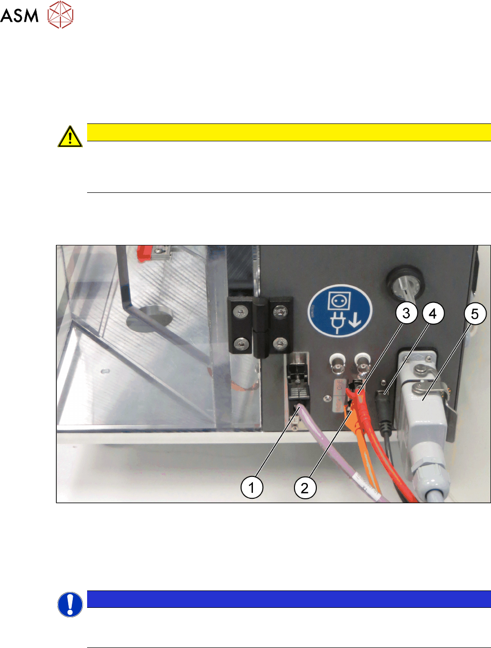
Cable connections at the right side of the HCS head unit
► Connect the cables to the interface on the right side of the HCS head unit as shown in the fol-
lowing picture:
Fig.32: HCS head unit – right side view
1 CAN-Bus cable [03159108-xx] 2 Hotlink cable [03148066-xx]
3 GigE cable [03148067-xx] 4 USB cable [03148065-xx]
5 Connection cable HCS [03152929-xx]
NOTICE
GigE or Hotlink cable
Depending on the camera of the placement head, either connect the GigE cable or the hot-
link cable.
4 Setting up and commissioning
4.2 Setting up the HCS
User Manual SIPLACE Head Care Station 10/2017 47
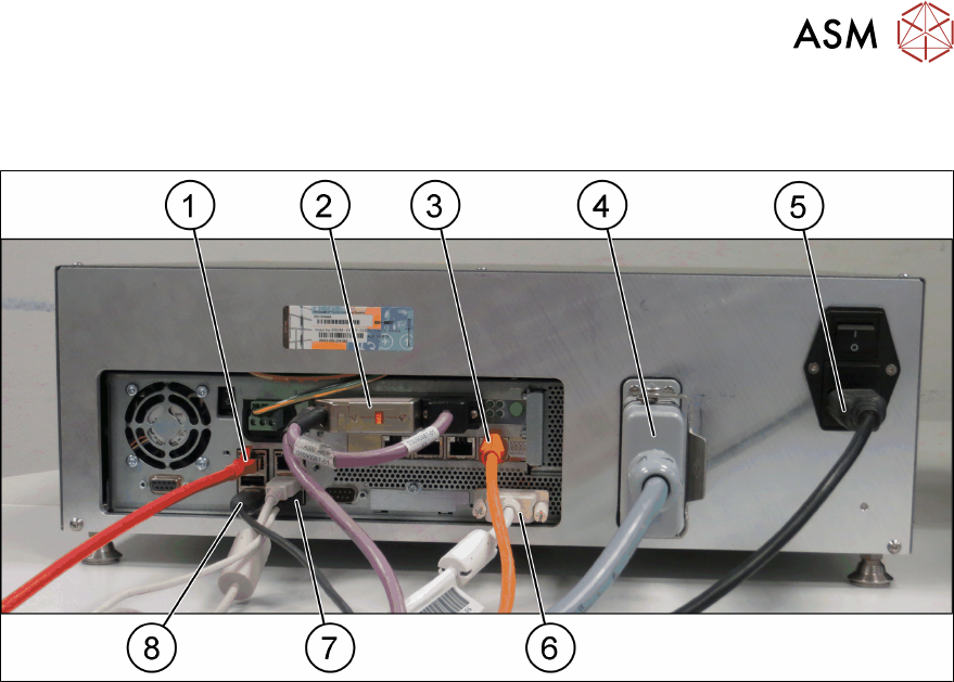
Cable connections at the control box
► Connect the cables to the interfaces on the control box as shown in the following picture:
Fig.33: Control box
1 GigE cable [03148067-xx] 2 CAN-Bus cable [03159108-xx]
3 Hotlink cable [03148066-xx] 4 Connection cable HCS [03152929-xx]
5 Mains power cord [00375711-xx] 6 DVI monitor cable
7 USB keyboard / USB mouse 8 USB cable [03148065-xx]
4 Setting up and commissioning
4.2 Setting up the HCS
48 User Manual SIPLACE Head Care Station 10/2017
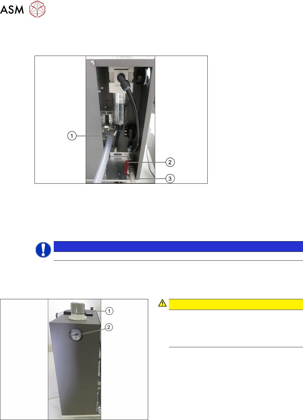
4.2.2 Pneumatic connections
► Connect the vacuum pump or compressed air supply to the pneumatic unit as shown in the
following picture:
Fig.34: Pneumatic unit
1 Spiral coiled tube for vacuum pump con-
nection
2 Main valve for compressed air supply
3 1/2" tube for compressed air generator
connection
NOTICE
Input valves not closed
Ensure the input valves are closed when connecting either the compressed air supply or the va-
cuum pump.
4.2.3 Adjusting the pneumatic supply
Fig.35: Adjustment wheel and manometer
CAUTION!
Risk of injury due to loose pneumatic hoses!
Always ensure that the valves of the pneu-
matic connections for the heads are closed
before opening the main valve for com-
pressed air.
.
► Ensure that all valves of the pneumatic connec-
tions for the heads are closed.
► Open the main valve of the compressed air sup-
ply.
► Pull off the cap(1) of the adjustment wheel.
► Turn the adjustment wheel until the mano-
meter(2) shows 4.8 bar.
► Push down the cap(1) of the adjustment wheel to
secure the setting.
► Close the main valve of the compressed air sup-
ply.