User Manual SIPLACE Head Care Station -.pdf - 第48页
4 Setting up and commissioning 4.2 Setting up the HCS 48 User Manual SIPLACE Head Care Station 10/2017 4.2.2 Pneumatic connections ► Connect the vacuum pump or compressed air supply to the pneumatic unit as shown in the …
4 Setting up and commissioning
4.2 Setting up the HCS
User Manual SIPLACE Head Care Station 10/2017 47
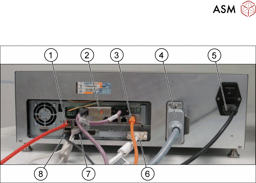
Cable connections at the control box
► Connect the cables to the interfaces on the control box as shown in the following picture:
Fig.33: Control box
1 GigE cable [03148067-xx] 2 CAN-Bus cable [03159108-xx]
3 Hotlink cable [03148066-xx] 4 Connection cable HCS [03152929-xx]
5 Mains power cord [00375711-xx] 6 DVI monitor cable
7 USB keyboard / USB mouse 8 USB cable [03148065-xx]
4 Setting up and commissioning
4.2 Setting up the HCS
48 User Manual SIPLACE Head Care Station 10/2017
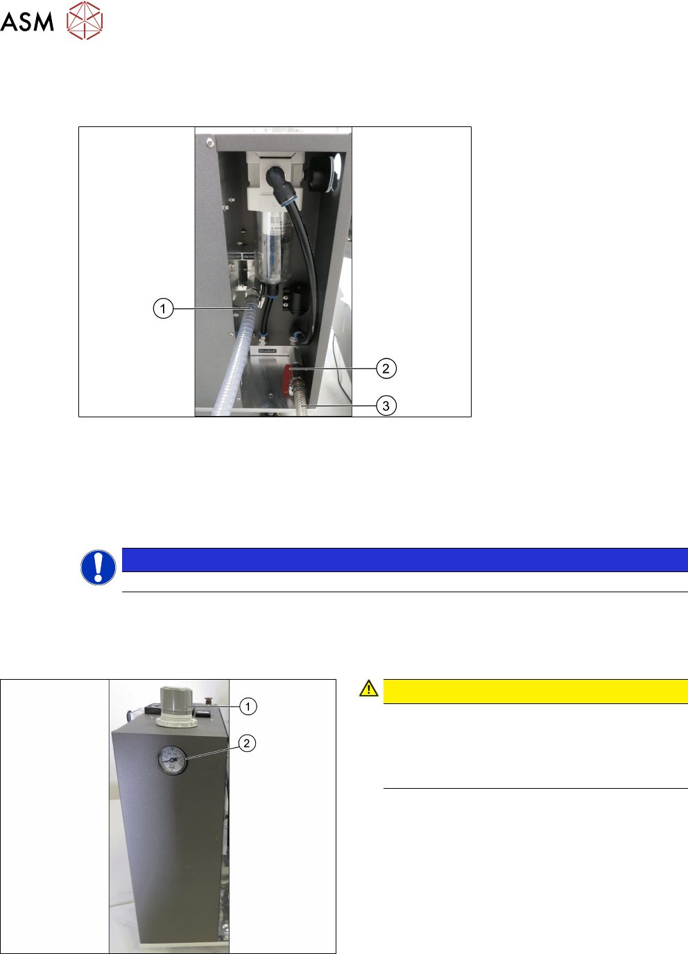
4.2.2 Pneumatic connections
► Connect the vacuum pump or compressed air supply to the pneumatic unit as shown in the
following picture:
Fig.34: Pneumatic unit
1 Spiral coiled tube for vacuum pump con-
nection
2 Main valve for compressed air supply
3 1/2" tube for compressed air generator
connection
NOTICE
Input valves not closed
Ensure the input valves are closed when connecting either the compressed air supply or the va-
cuum pump.
4.2.3 Adjusting the pneumatic supply
Fig.35: Adjustment wheel and manometer
CAUTION!
Risk of injury due to loose pneumatic hoses!
Always ensure that the valves of the pneu-
matic connections for the heads are closed
before opening the main valve for com-
pressed air.
.
► Ensure that all valves of the pneumatic connec-
tions for the heads are closed.
► Open the main valve of the compressed air sup-
ply.
► Pull off the cap(1) of the adjustment wheel.
► Turn the adjustment wheel until the mano-
meter(2) shows 4.8 bar.
► Push down the cap(1) of the adjustment wheel to
secure the setting.
► Close the main valve of the compressed air sup-
ply.

4 Setting up and commissioning
4.3 Software HCS
User Manual SIPLACE Head Care Station 10/2017 49
4.3 Software HCS
4.3.1 Installing the operating system
To install the Windows Embedded Standard 7 (WES7) operating system, please follow the in-
stallation instructions in “Operating System Windows Embedded Standard 7”[00197737-xx].
4.3.2 Installing the HCS software
This section describes the installation of the HCS interface with a boot capable USB flash drive.
Other means for installing the interface may differ in the following procedure:
Fig.36: Software download
► Download the HCS software from the license
portal.
► Unzip the file onto a USB flash drive.
► Plug in the USB drive into a free slot at the con-
trol box.
Fig.37: Language selection
► To start the installation, double-click the
setup.exe on the USB flash drive and follow the
instructions on the screen.
► Choose the installation language.
► Click OK to continue.
Fig.38: HCS UI installation start screen
► Click on the HeadcareStation icon.
► Click Next to continue.
ð The software prepares and installs all neces-
sary software components. When the installa-
tion is complete, the Sirio installation starts
automatically.