User Manual SIPLACE Head Care Station -.pdf - 第54页
5 Working with the HCS 5.2 Head verification process 54 User Manual SIPLACE Head Care Station 10/2017 5.2 Head verification process For a typical head verification, the following steps need to be performed: ► 5.2.1 "…
5 Working with the HCS
5.1 Remote desktop operation
User Manual SIPLACE Head Care Station 10/2017 53
5 Working with the HCS
CAUTION
Qualified or adequately trained personnel
► No one may start up, operate or otherwise work on the HCS unless they have the rel-
evant qualification. Using the HCS not as prescribed, could endanger life and limb,
and result in material damage.
► The qualification must be proven by means of training courses or instructions for the
personnel. The instructions are to be given by personnel trained and authorized by
ASM SMT Solutions Team. For an overview of the training courses, refer to section
1.2 "Qualification and training of personnel" [}10].
1.1.5 "Failure to use as prescribed" [}9]
5.1 Remote desktop operation
Instead of using a separate monitor, keyboard and mouse, the HCS can also be operated remotely
using the Windows XP remote desktop function. To establish a remote desktop connection to the
HCS control box, proceed as follows:
► Connect your notebook or PC to the HCS control box with a LAN cable.
► When the network card is trying to obtain an IP address, you have to wait until this icon
is displayed in the taskbar of your desktop.
► Click Start > Programs > Accessories > Communications > Remote Desktop Connec-
tion.
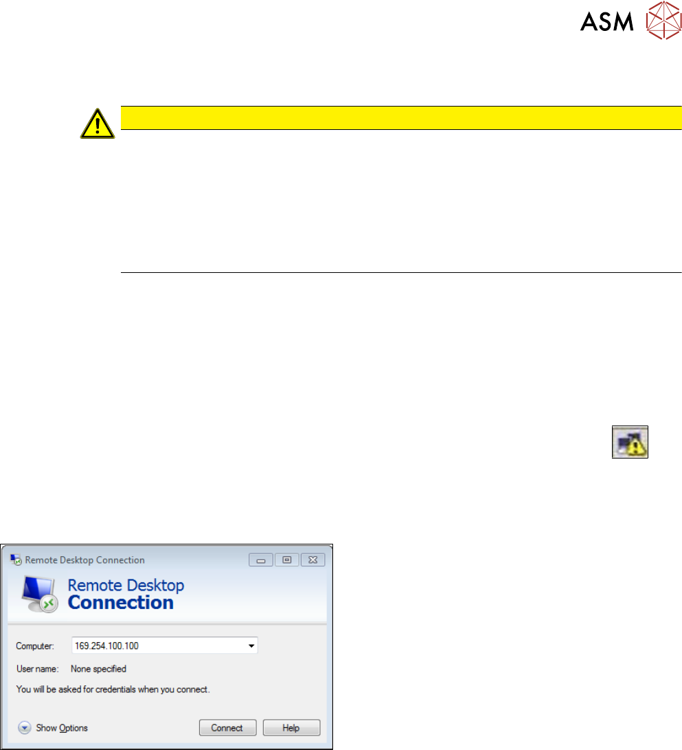
ð The Remote Desktop Connection dialog box is displayed:
► In the Remote Desktop Connection dialog box,
enter the standard IP-address 169.254.100.100
and click Connect.
ð A remote desktop connection is built up.
► In the HCS login dialog box, log on as follows:
Username: operator
Password: operator
5 Working with the HCS
5.2 Head verification process
54 User Manual SIPLACE Head Care Station 10/2017
5.2 Head verification process
For a typical head verification, the following steps need to be performed:
► 5.2.1 "Setting up the heads" [}54]
► 5.2.2 "Switching on the HCS" [}61]
► 5.2.3 "Starting the HCS software" [}62]
► 5.2.4 "Changing the user role" [}64]
► 5.2.5 "Check / adjust the force sensor reference voltage" [}64]
► 5.2.6 "Verifying a head" [}66]
5.2.1 Setting up the heads
This chapter describes how to set up a placement head at the HCS head unit.
DANGER
Checking for absence of voltage!
► Before you start working, switch off the main power switch at the control box to ensure
the absence of voltage!
5.2.1.1 Setting up C&P20x and CPP heads
As the assembly is almost identical for a C&P20x or a CPP head, the description was made on the
example of the C&P20P head pointing out the differences in the appropriate places.
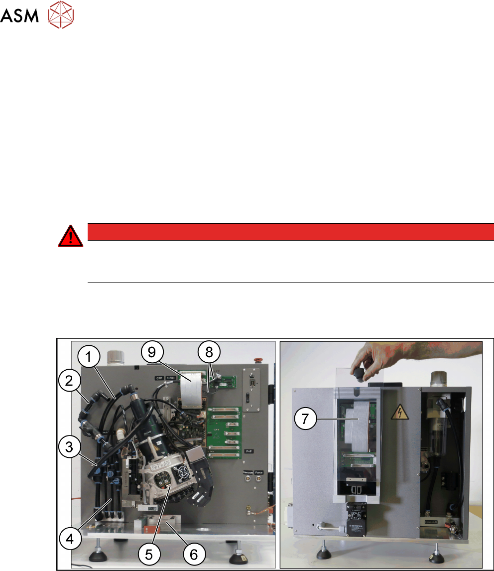
Fig.44: C&P20P head mounted at the HCS
1 Hose for compressed air supply to head 2 Hose for vacuum supply
3 Exhaust air hose 4 Hose for compressed air supply to PRV
5 Placement head with calibration nozzles
and component camera
6 Stopper for CP20x and CPP heads
7 Flat ribbon cable connecting head inter-
face and head adapter
8 Camera cables for hotlink connection
9 Flat ribbon cable to the head interface
5 Working with the HCS
5.2 Head verification process
User Manual SIPLACE Head Care Station 10/2017 55
NOTICE
Calibration nozzle
For the head verification, the head must be equipped with calibration nozzles.
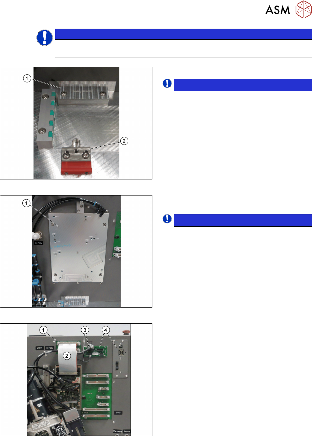
Fig.45: Inserting the stopper
► Insert the correct stopper(1).
NOTICE!
The tool clamping(2) has two different ver-
sions: The new tool locking using a spring,
the former tool locking using a screw.
.
Fig.46: Mounting the head
► Fasten the screws to the head mounting
board(1) with a torque of 2.7Nm.
NOTICE!
The screw holes to be used for the various
heads are indicated on the board.
.
Fig.47: Connecting the cables
Connections at the front:
► Connect the flat ribbon cable(2) to the board ad-
apter head interface(1).
► Connect the camera cables(3) to the respective
camera interface (4).