User Manual SIPLACE Head Care Station -.pdf - 第55页
5 Working with the HCS 5.2 Head verification process User Manual SIPLACE Head Care Station 10/2017 55 NOTICE Calibration nozzle For the head verification, the head must be equipped with calibration nozzles. Fig.45: Inse…
5 Working with the HCS
5.2 Head verification process
54 User Manual SIPLACE Head Care Station 10/2017
5.2 Head verification process
For a typical head verification, the following steps need to be performed:
► 5.2.1 "Setting up the heads" [}54]
► 5.2.2 "Switching on the HCS" [}61]
► 5.2.3 "Starting the HCS software" [}62]
► 5.2.4 "Changing the user role" [}64]
► 5.2.5 "Check / adjust the force sensor reference voltage" [}64]
► 5.2.6 "Verifying a head" [}66]
5.2.1 Setting up the heads
This chapter describes how to set up a placement head at the HCS head unit.
DANGER
Checking for absence of voltage!
► Before you start working, switch off the main power switch at the control box to ensure
the absence of voltage!
5.2.1.1 Setting up C&P20x and CPP heads
As the assembly is almost identical for a C&P20x or a CPP head, the description was made on the
example of the C&P20P head pointing out the differences in the appropriate places.
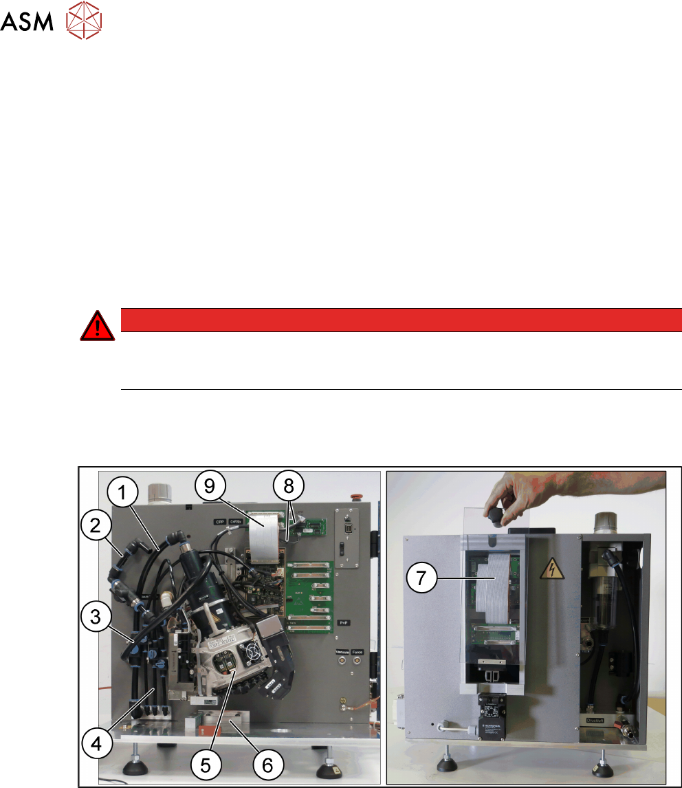
Fig.44: C&P20P head mounted at the HCS
1 Hose for compressed air supply to head 2 Hose for vacuum supply
3 Exhaust air hose 4 Hose for compressed air supply to PRV
5 Placement head with calibration nozzles
and component camera
6 Stopper for CP20x and CPP heads
7 Flat ribbon cable connecting head inter-
face and head adapter
8 Camera cables for hotlink connection
9 Flat ribbon cable to the head interface
5 Working with the HCS
5.2 Head verification process
User Manual SIPLACE Head Care Station 10/2017 55
NOTICE
Calibration nozzle
For the head verification, the head must be equipped with calibration nozzles.
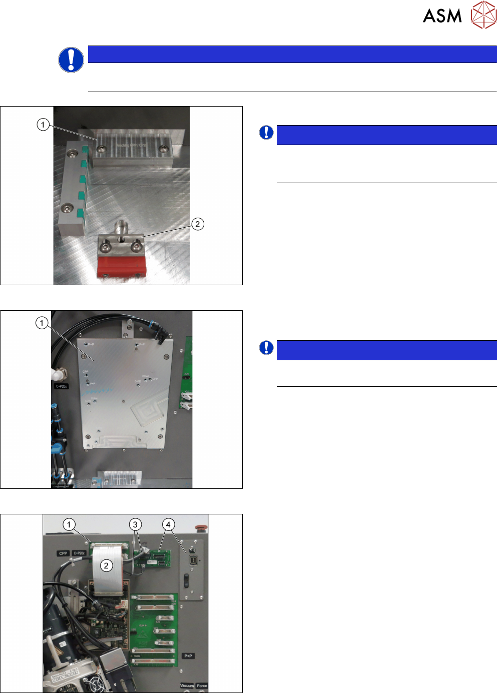
Fig.45: Inserting the stopper
► Insert the correct stopper(1).
NOTICE!
The tool clamping(2) has two different ver-
sions: The new tool locking using a spring,
the former tool locking using a screw.
.
Fig.46: Mounting the head
► Fasten the screws to the head mounting
board(1) with a torque of 2.7Nm.
NOTICE!
The screw holes to be used for the various
heads are indicated on the board.
.
Fig.47: Connecting the cables
Connections at the front:
► Connect the flat ribbon cable(2) to the board ad-
apter head interface(1).
► Connect the camera cables(3) to the respective
camera interface (4).
5 Working with the HCS
5.2 Head verification process
56 User Manual SIPLACE Head Care Station 10/2017
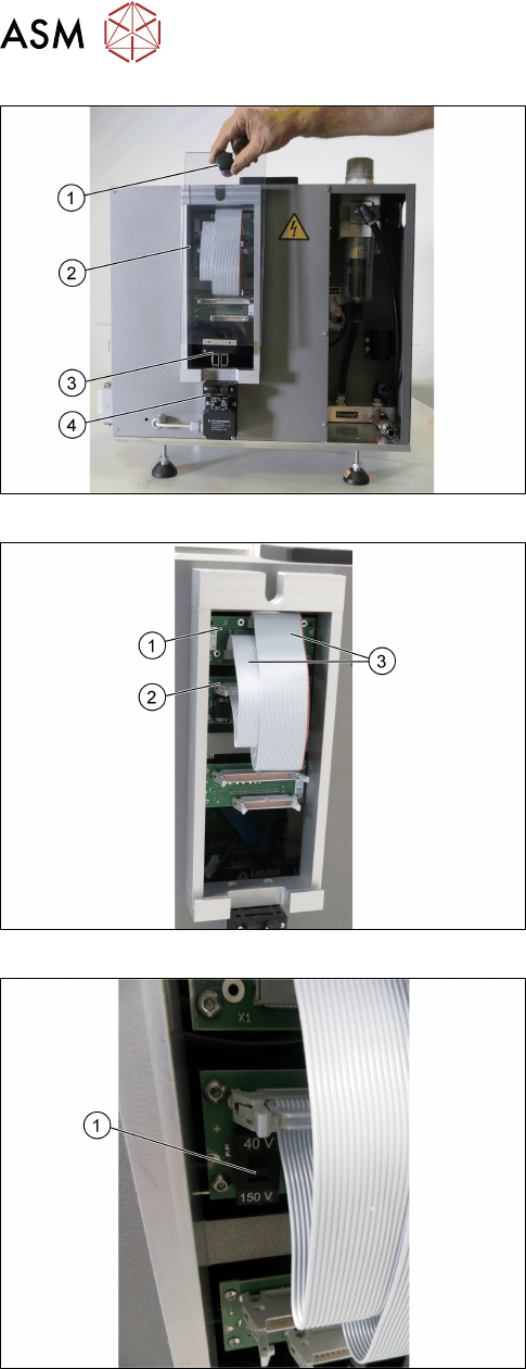
Fig.48: Removing the cover
Connections at the back:
► Grab the knob(1) and pull the protective
cover(2) with the actuator(3) upwards out of the
safety switch(4).
Fig.49: Connecting the flat ribbon cablesr
► Connect the flat ribbon cables(3) of the Board
Adapter-LP C700B-HCSII[03087842-xx](1) to
the Board Adapter-LP CPP/CP20-HC-
SII[03087843-xx](2).
Fig.50: Setting the voltage
► For C&P20x heads, set the switch(1) to 40V.
► For CPP heads, set the switch(1) to 150V.