User Manual SIPLACE Head Care Station -.pdf - 第60页
5 Working with the HCS 5.2 Head verification process 60 User Manual SIPLACE Head Care Station 10/2017 Fig.59: Removing the cover Connections at the back: ► Grab the knob (1) and pull the protective cover (2) with the …
5 Working with the HCS
5.2 Head verification process
User Manual SIPLACE Head Care Station 10/2017 59
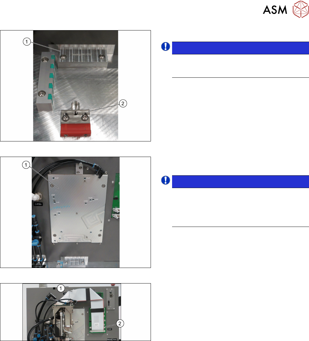
Fig.56: Inserting the stopper
► Insert the correct stopper(1).
NOTICE!
The tool clamping(2) has two different ver-
sions: The new tool locking using a spring,
the former tool locking using a screw.
.
Fig.57: Mounting the head
► Fasten the screws to the head mounting
board(1) with a torque of 2.7Nm.
NOTICE!
The screw holes to be used for the various
heads are indicated on the board.
Thread missing! The screw at the right bottom
cannot be fixed as the mounting board is not
provided with the corresponding thread.
.
Fig.58: Connecting the cables
Connections at the front:
► Connect the flat ribbon cable(2) to the board ad-
apter head interface(1).
5 Working with the HCS
5.2 Head verification process
60 User Manual SIPLACE Head Care Station 10/2017
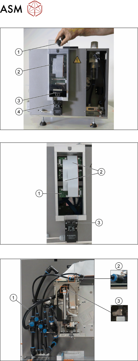
Fig.59: Removing the cover
Connections at the back:
► Grab the knob(1) and pull the protective
cover(2) with the actuator(3) upwards out of the
safety switch(4).
Fig.60: Connecting the flat ribbon cables
► Connect the flat ribbon cables(2) of the Board
Adapter-LP C700B-HCSII[03087842-xx] to the
Board Adapter-LP DLM4/TWIN-HC-
SII[03087844-xx](1).
► Fit the cover back on.
► Make sure that the actuator snaps back into the
safety switch(3).
Fig.61: Connecting the hoses
► Connect the hose for the exhaust air to the
head (1).
► Connect the hose for compressed air supply to
the head top(2).
► Connect the hose for compressed air supply to
the pressure regulator valve (PRV)(3).
For information on the correct pneumatic connections,
see 3.1.6.2 "Pneumatic connections for the
heads" [}41].
5 Working with the HCS
5.2 Head verification process
User Manual SIPLACE Head Care Station 10/2017 61
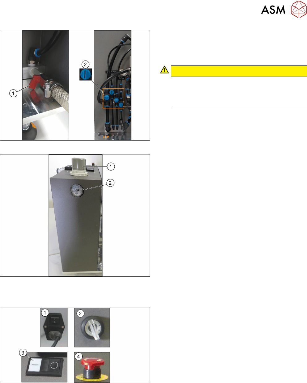
Fig.62: Opening the valves
► Open the main valve for the compressed air sup-
ply(1) at the back of the head unit.
► Open the respective valves(2) for the com-
pressed air supply to the head.
CAUTION!
Risk of injury due to loose pneumatic hoses!
Always ensure the valves of the pneumatic con-
nections for the heads are closed before switch-
ing on the main valve for compressed air.
.
For information on the correct pneumatic connections,
see 3.1.6.2 "Pneumatic connections for the
heads" [}41].
Fig.63: Adjustment wheel and manometer
► Pull off the cap(1) of the adjustment wheel.
► Turn the adjustment wheel until the mano-
meter(2) shows 4.8 bar.
5.2.2 Switching on the HCS
Fig.64: HCS switches and buttons
► Switch on the main switch(1) on the control box.
► Switch on the HCS power switch(2) on the right
side of the head unit to power on the head unit.
► Ensure that the EMERGENCY OFF button(4) is
released.
► Press the Start button(3) on top of the head unit.
► Wait until the head is initialized.
ð Green LEDs at the intermediate distributor
board light up and for C&P heads, the LEDs
at the DPs flash when the head is initialized.