3OM-1208-011_w.pdf - 第101页
3-14 AIVEDT -ID (A01_1 1) Input Conveyor Y Position arrange speed setup (% deceleration) [%] Set the deceleration rate of the input conveyor Y arrangement speed in this text box. (A01_12) Output Conveyor Y Position arran…
3-13
AIVEDT-ID
0 0
00
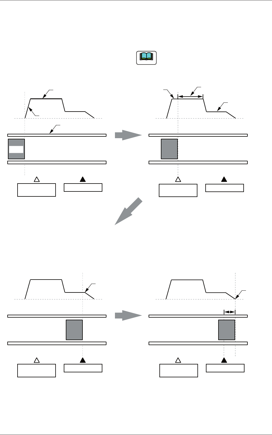
2. When the PCB is detected by the deceleration
sensor, the speed of the transfer conveyor
starts to decelerate to the specified one (Speed
2 [mm/sec]) after the period of time specified as
"Timer [mm/sec]" has elapsed.
1. The speed "Speed 1 [mm/sec]" of the
transfer conveyor is accelerated at the
specified "Acceleration [G]" and PCBs
are transferred at the accelerated speed.
The speed from "Speed 1 [mm/sec]" to
"Speed 2 [mm/sec]" is equivalent to
"Acceleration [G]".
Note
Position
Speed
Speed 1
Acceleration
Time
Conveyor
PCB
Deceleration
Sensor
Stop Sensor
Speed 1
Time
Speed
Speed 2
Timer
Deceleration
Sensor
Stop Sensor
3. When the PCB is detected by the stop
sensor, the transfer speed decreases and
the PCB is transferred to the stop position
specified as "Position [mm]".
4. The PCB stops completely.
Speed
Time
Deceleration
Sensor
Stop Sensor
Starting of
PCB Stop
Speed
Time
Deceleration
Sensor
Stop Sensor
PCB
Stop
Position
Fig. 3C15
0606-009
1.2 Operation Data

3-14
AIVEDT-ID
(A01_11)
Input Conveyor
Y Position arrange speed setup (% deceleration) [%]
Set the deceleration rate of the input conveyor Y arrangement speed in
this text box.
(A01_12)
Output Conveyor
Y Position arrange speed setup (% deceleration) [%]
Set the deceleration rate of the output conveyor Y arrangement speed in
this text box.
(A01_13)
PCB locate mode
Stage 1, Stage 2
Operation
"Std" or "Specification value" can be selected for the PCB locating
operation.
In normal cases, select "Std".
Std :
The PCB locating operation is performed
according to the standard value specifi
ed for
the machine.
Specification value
:
The desired numerical value can be specified
for the PCB locating operation.
The 1st sp dclr setting([%] deceleration) [%]
Set the deceleration rate of the backup base movement in this text box.
The specified value is refl
ected for the first action (first one of the two-
step actions) taken in the PCB locating operation.
When the locating
operation is released, the value is reflected for the second action.
The 2nd sp dclr setting([%] deceleration) [%]
Set the deceleration rate of the backup base movement in this text box.
The specified value is reflected for the second action (second one of
the two-step actions) taken in the PCB locating operation. When the
locating operation is released, the value is reflected for the fi
rst action.
0606-009
1.2 Operation Data

3-15
AIVEDT-ID
Z Clamp
Delay Timer 1 [msec]
Set the delay time to start the upward movement of the Z clamp after
the backup base has started moving up as the second action.
Delay Timer 2 [msec]
Set the period of time during which the Z clamp is released after
completion of component placement. The backup base starts moving
down after this unclamping operation is completed.
Operation waiting time [msec]
Set the waiting time to be spent before the Z clamp is activated.
(A01_14)
Placement mode
(Not Available)
Stage 1, Stage 2
Select either "Placement" or "Pass" as a placement mode for each stage.
In normal cases, select "Placement"
Placement :
The machine is set in the "PLACE" mode.
Pass :
The machine is set in the "P
ASS" mode.
When "Pass" is set in this text box and the pattern program data is
selected as current one, the vacuum pump is automatically turned off.
0606-009
1.2 Operation Data