3OM-1208-011_w.pdf - 第147页
3-60 AIVEDT -ID 2.4.3 Deletion of Allocated Component ID (1) Select the desired "Feeder Base #" tab and the feeder No. (Fdr No.) of the component to be deleted. The selected line (Fdr No.) turns blue, indicatin…
3-59
AIVEDT-ID
0606-009
2.4.2 Allocation of Component IDs
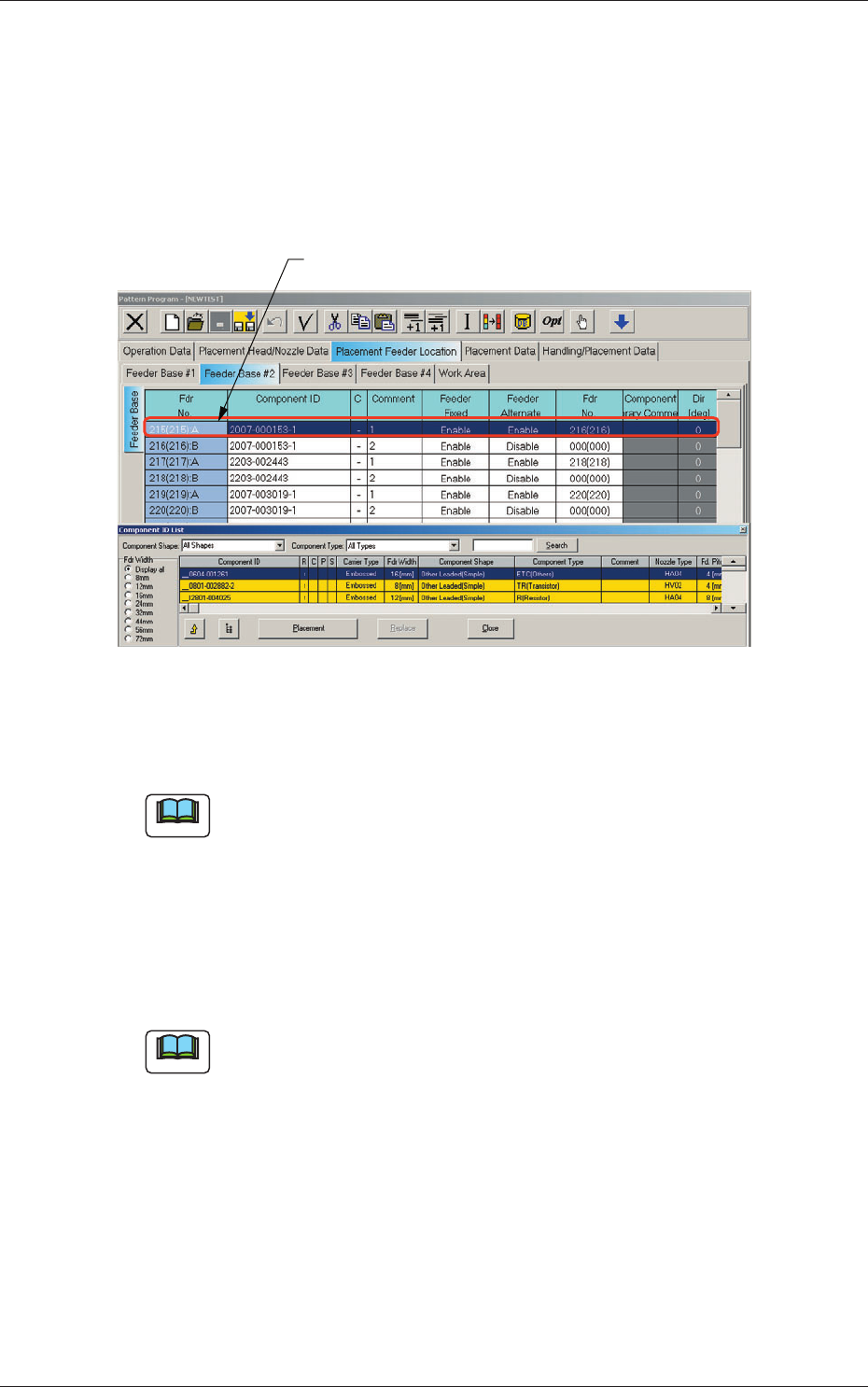
(1) Select the "Feeder Base #" tab where a component ID should be
allocated.
(2) Select the feeder No. (Fdr No.) where a component ID should be
allocated.
The selected line (Fdr No.) turns blue, indicating that it is selected.
Selected Fdr No.
Fig. 3C47 Edit Window (Example)
(3) Select the desired component ID to be allocated in the "Component ID
List" window.
Note
When parameters are set in the "Component Shape" and "Component
Type" combo boxes and an option button in the "Fdr Width" group box is
selected, the component IDs based on the selections will be searched and
displayed quickly.
(4) Press the [Placement] button.
The selected component ID is allocated to the "Fdr No." line that has
turned blue.
Note
When the [Replace] button is pressed in place of the [Placement] button,
the component ID in the "Component ID" text box is replaced with the
component ID selected from the list of component IDs.
2.4 Allocation of Component IDs
3-60
AIVEDT-ID
2.4.3 Deletion of Allocated Component ID
(1) Select the desired "Feeder Base #" tab and the feeder No. (Fdr No.) of
the component to be deleted.
The selected line (Fdr No.) turns blue, indicating that it is selected.
(2) Select the [Cut] icon on the toolbar. The selected feeder No. (Fdr No.)
is deleted and the subsequent feeder Nos. are shifted up.
2.4.4 Setting of Dual Feeder Mode
(1) Select the range of "Fdr Nos." to be specified as dual feeders.
(2) When the right button of the track ball is pressed with the range being
selected, a menu opens.
(3) Select "Set Up Dual Feeder" from the menu.
": A" or ": B" is assigned to "Fdr No." of the lines in the selected range.
Note
(a) Clicking the icon ( ) on the extended toolbar with a range of
feeders being selected also makes it possible to set the feeders in the
dual feeder mode.
(b) When a component ID of "Feeder Width: 8 mm" is allocated, "Dual
Feeder" is automatically set and ": A" or ": B" is added to the feeder
No. (Fdr No.).
2.4.5 Cancellation of Dual Feeder Mode
(1) Select the lines (Fdr Nos.) to cancel the dual feeder mode.
(2) When the right button of the track ball is pressed with the range being
selected, a menu opens.
(3) Select "Release Dual Feeder" from the menu.
The selected lines (Fdr Nos.) are released from the dual feeder mode.
Note
(a) Clicking the icon ( ) on the extended toolbar with a range of
feeders being selected also makes it possible to release the feeders
from the dual feeder mode.
(b) It is impossible to cancel the setting of "Dual Feeder" for the feeder
No. (Fdr No.) where a component ID of "Feeder Width: 8 mm" is
allocated.
0606-009
2.4 Allocation of Component IDs
3-61
AIVEDT-ID
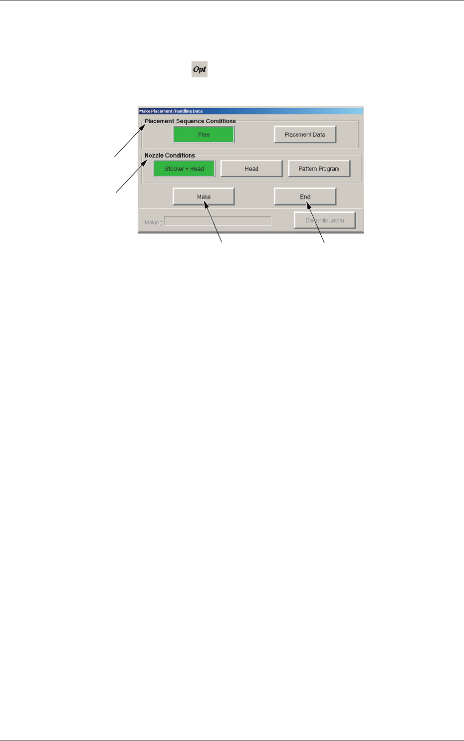
2.5 Optimization of Pattern Program
The currently opened pattern program can be optimized.
When the optimize icon (
) is pressed in the "Pattern Program" edit
window, the "Make Placement/Handling Data" dialog box opens.
[3]
[1]
[4]
[2]
Fig. 3C48 "Make Placement/Handling Data" Dialog Box
[1] "Placement Sequence Conditions" Group Box
The order of component placement for the optimization can be
specified.
[Free] Button
When selected, this makes it possible to create the data that will
enable the component placement based on the production tact
(priority).
Note:
When "Block Sort" is set up for the placement data, the
order of component placement based on "Block Sort" takes
priority.
[Placement Data] Button
When selected, this makes it possible to create the data that will
enable the component placement in the order specified in the
placement data.
Note:
When "Block Sort" is set up for the placement data, the
order of component placement based on "Block Sort" takes
priority.
0606-009
2.5 Optimization of Pattern Program