3OM-1208-011_w.pdf - 第164页
3-77 AIVEDT -ID 3.4 Data for Polar Coordinate Conversion Function When unit PCBs are arranged at arbitrary angles on a multi-unit PCB, this function converts polar coordinates after parameters (arrangement angle of each …
3-76
AIVEDT-ID
(5) Creation of Placement Data
•
Model A
A program must be created such that the machine places components
repeatedly on three identical patterns.
Create the data in the same way as described in "3.2 Repetitive Patterns
(Image Recognition Enabled)".
Note
(a) It is required to create the following placement data.
•
P-data (U01)
•
O-data (U01)
(b) Each pattern origin (coordinates) must be based on the placement
coordinate reference.
•
Model B
A program must be created such that the machine places components
repeatedly on four identical patterns.
Create the data in the same way as described in "3.2 Repetitive Patterns
(Image Recognition Enabled)".
Note
(a) It is required to create the following placement data.
•
P-data (U02)
•
O-data (U02)
(b) Each pattern origin (coordinates) must be based on the placement
coordinate reference.
•
Model C
Although this is a single pattern, regard this as a single repetitive pattern
and follow the same procedure as described in "3.2 Repetitive Patterns
(Image Recognition Enabled)" to create the data for this model.
Note
It is required to create the following placement data.
•
P-data (U03)
•
O-data (U03)
(6) O-data (U03)
Table 3C19
O-No. X [mm] Y [mm] Z = theta [deg] H C Comment
1 0X
3
0Y
3
+000.00 +0.000 -
2 +000.000 +000.000 +000.00 +0.000 E
0606-009
3.3 Multi-Model Repetitive Patterns
3-77
AIVEDT-ID
3.4 Data for Polar Coordinate Conversion Function
When unit PCBs are arranged at arbitrary angles on a multi-unit PCB, this
function converts polar coordinates after parameters (arrangement angle of
each pattern) are entered in the "Z=theta [deg]" text boxes of the O-data.
Follow the same procedure as described in "3.2 Repetitive Patterns (Image
Recognition Enabled)" to create the data, except for the placement data
(O-data).
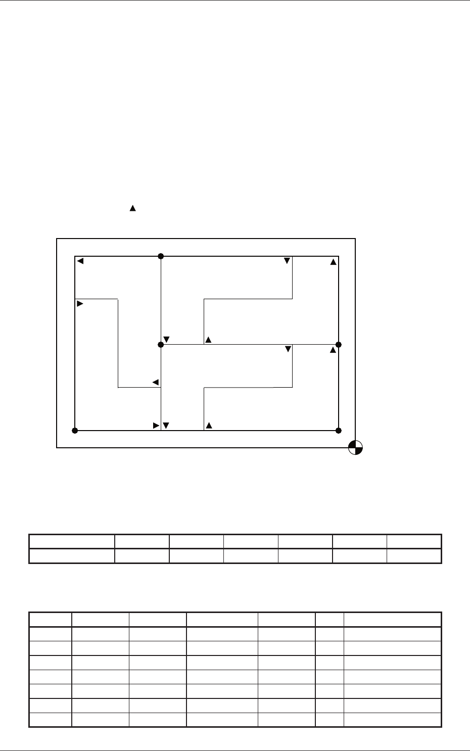
(1) Information on Pattern Program Creation
•
Example of Patterns
O4
O1
O3
O2
O6
O5
X3 X2 X1
Y1
Y2
Y3
Placement
Coordinate
Reference
Pattern 5
(90�)
Patterns is a fiducial mark.
Pattern 1 is assumed as "0�".
Pattern 6
(270�)
Pattern 4 (180�)
Pattern 3 (0�)
Pattern 2 (180�)
Pattern 1 (0�)
Fig. 3C57
•
Coordinates of Each Pattern Origin
Table 3C20
Pattern Origin 0
1
0
2
0
3
0
4
0
5
0
6
Coordinates (X
1
, Y
1
) (X
2
, Y
2
) (X
1
, Y
2
) (X
2
, Y
3
) (X
2
, Y
3
) (X
3
, Y
1
)
(2) Creation of O-Data
Table 3C21
O-No. X [mm] Y [mm] Z = theta [deg] H C Comment
1 X
1
Y
1
+000.00 +0.000 -
2 X
2
Y
2
+180.00 +0.000 -
3 X
1
Y
2
+000.00 +0.000 -
4 X
2
Y
3
+180.00 +0.000 -
5 X
2
Y
3
+090.00 +0.000 -
6 X
3
Y
1
+270.00 +0.000 -
7 +000.000 +000.000 +000.00 +0.000 E
0606-009
3.4 Data for Polar Coordinate Conversion Function

3-78
AIVEDT-ID
3.5 Placement Data for Block Sorting Function
Placement steps are grouped into some blocks and component placement
sequence can be specified for each block.
The following describes the method of block sorting according to the outside
diameters of the nozzles.
•
Outside Diameters of Nozzles
After the nozzle IDs in the placement feeder location data are confirmed,
the outside diameters are examined, using the nozzle type data of the
placement head/nozzle data.
•
Nozzle Type Data
Press the [MACH SET] button on the main menu bar of the "SYSTEM >>
DISPLA
Y SETTING" window and select the [NOZ. DATA] button on the
submenu bar.
Press the "Nozzle Data" tab in the "Nozzle Data" window.
Follow the same procedure as described in "3.2 Repetitive Patterns (Image
Recognition Enabled)" to create the data, except for the placement data
(P-data).
0606-009
3.5 Placement Data for Block Sorting Function