3OM-1208-011_w.pdf - 第241页
6-8 AIVEDT -ID [1] Support pin up/down NA and NC B1 and B2 [mm] This is the offset data for the origin position of the support pin up/down axis which ascends or descends during PCB positioning. A plu s (+) value decrease…
6-7
AIVEDT-ID
[5]
[6]
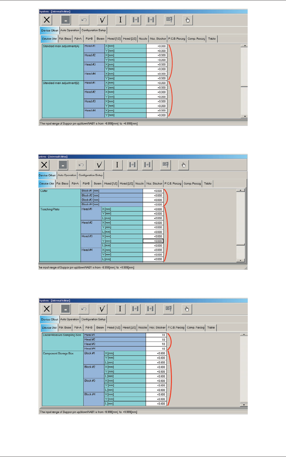
Fig. 3F6 "Device Offset" Tab Sheet (3)
[8]
[7]
Fig. 3F7 "Device Offset" Tab Sheet (4)
[10]
[9]
Fig. 3F8 "Device Offset" Tab Sheet (5)
0606-009
2.1 Device Offset Data
6-8
AIVEDT-ID
[1] Support pin up/down
NA and NC
B1 and B2 [mm]
This is the offset data for the origin position of the support pin up/down
axis which ascends or descends during PCB positioning.
A plu
s (+) value decreases the ascending stroke during PCB positioning.
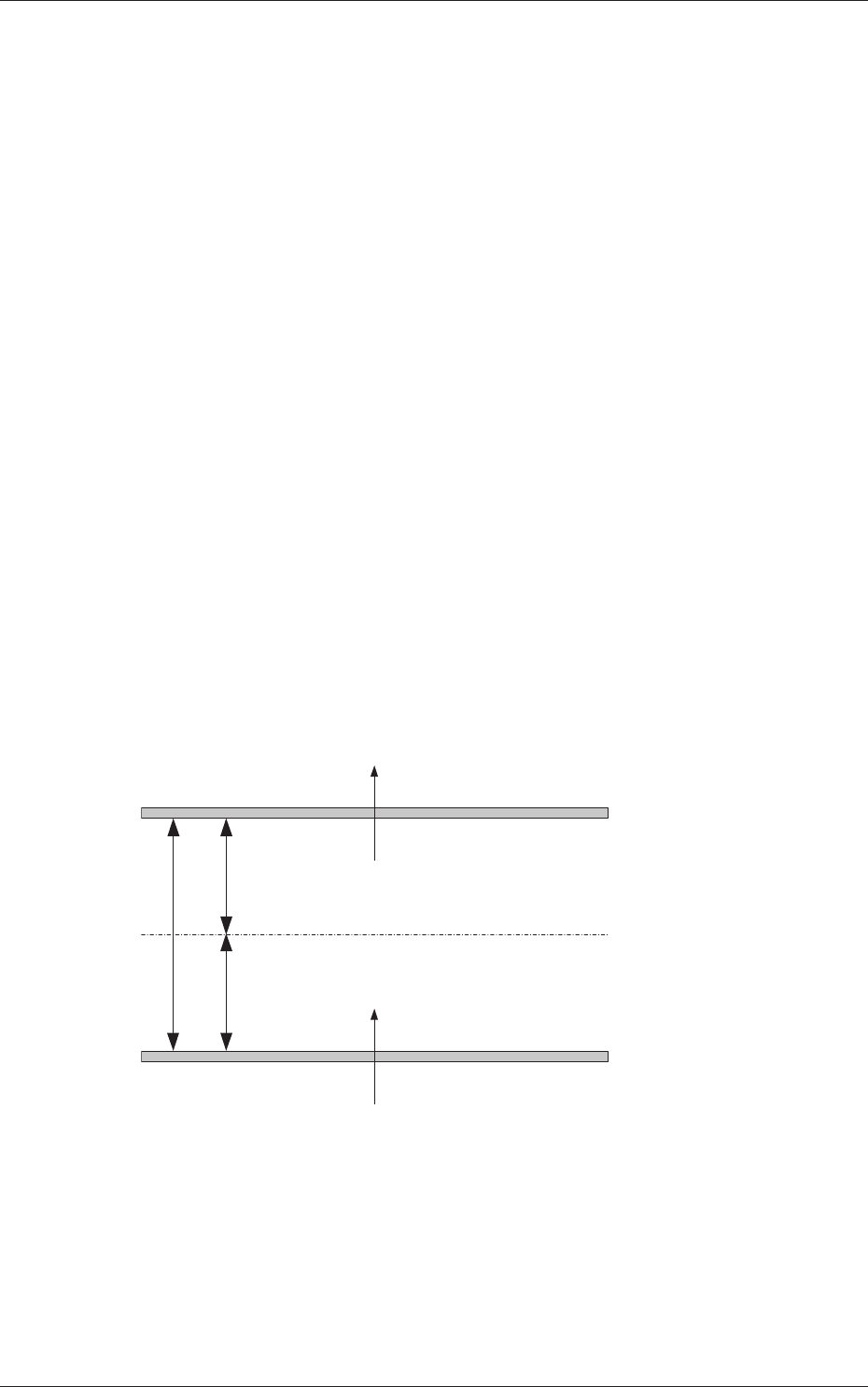
[2] Conveyor Width
NL, NB and NR
W1 and W2 [mm]
This offset is used to adjust the conveyor width to the absolute values.
When the conveyor width is set up to the specified one based on
the positioning center, a difference will be caused in the dimension
between the actually measured value (the distance between the machine
p
ositi
oning center and each chute) and the half of the specified width. In
this case, enter the difference in each text box.
W1 Offset :
A plus value must be entered when the actually
measured width is narrower than the half of the
specified one.
W2 Offset :
A minus value must be entered when the actually
measured width is narrower than the half of the
specified one.
A
A/2
A/2
NL-W1
NR-W1
NB-W1
NL-W2
NR-W2
NB-W2
(+)
(-)
(+)
(-)
Fig. 3F9
0606-009
2.1 Device Offset Data
6-9
AIVEDT-ID
0606-009
[3] PCB Transfer Positioning
Stage #1 and Stage #2
L->R1 (Back), R->L1 (Back),
L->R2 (Front), and R->L2 (Front) [mm]
Each parameters are used to correct the positional deviations in PCB
transfer positioning in comparison with "Support pin up/down".
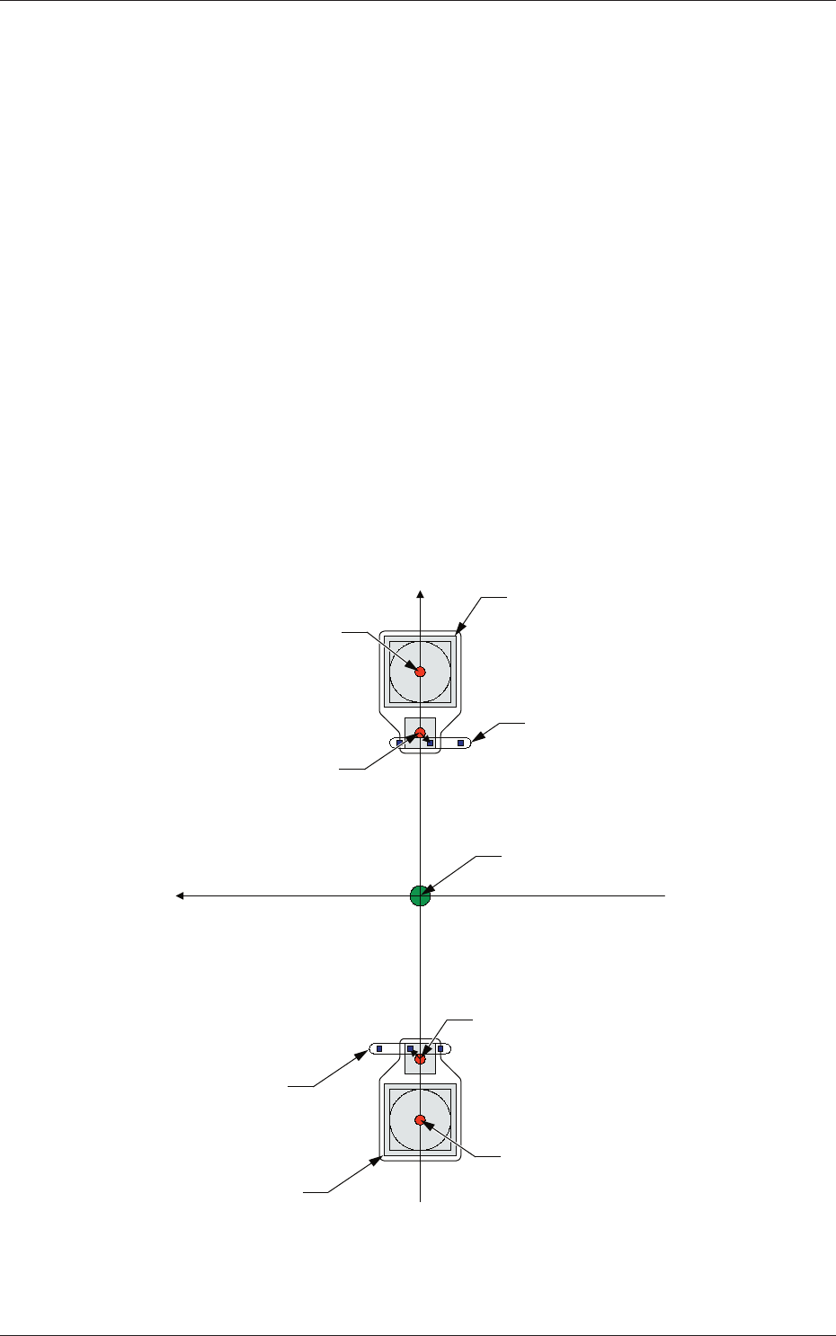
[4] Standard Mark
Head #1, Head #2, Head #3, and Head #4
Mark(L), Mark(M), Mark(R)
X(Horizontal) and Y(Vertical) [mm]
"Mark (M)" represents the standard mark position captured by the PEC
recognition camera when the rotational center of the head is moved to
the area above the component recognition camera.
"Mark (R)" and "Mark (L)" are the standard mark positions captured by
the PEC recognition camera when the pertinent nozzle is moved to the
center of the component recognition camera with the head being rotated
90
°
or 270
°
.
Xm (+)
Ym (+)
Component Recognition Camera
Component Recognition
Camera
Head Rotational Center
Head Rotational Center
Standard Mark
Standard Mark
Center of PEC Recognition Camera
Center of PEC Recognition
Camera
Pm. Machine Reference
Coordinate Origin
Fig. 3F10
2.1 Device Offset Data