3OM-1208-011_w.pdf - 第264页
6-31 AIVEDT -ID [3] Pu retention time [sec] Set a parameter to specify the time when the nozzle must be stopped at the lower limit for all component picks. Note Use th is function wh en components cannot be pic ked up in…
6-30
AIVEDT-ID
Head 1, Head 2, Head 3, and Head 4
[1] OFF [sec]
The specified parameter is used to adjust the timing to turn the vacuum
off while the NL-axis is descending for component placement.
When "+0.000" is specified in the "OFF" text box, the vacuum is turned
off when the NL-axis has reached 10 ms away from the bottom arrival
point.
Base on the point 10 ms away from the NL-axis bottom arrival point,
a plus value in the "OFF" text box means that the timing to turn off the
vacuum will be delayed. A minus value means that the timing will be
quickened.
[2] ON [sec]
The specified parameter is used to adjust the timing to turn the vacuum
on while the NL-axis is descending for component pick.
When "+0.000" is specified in the "ON" text box, the vacuum is turned
on when the NL-axis has reached 10 ms away from the bottom arrival
point.
Base on the point 10 ms away from the NL-axis bottom arrival point,
a plus value in the "ON" text box means that the timing to turn on the
vacuum will be delayed. A
minus value means that the timing will be
quickened.
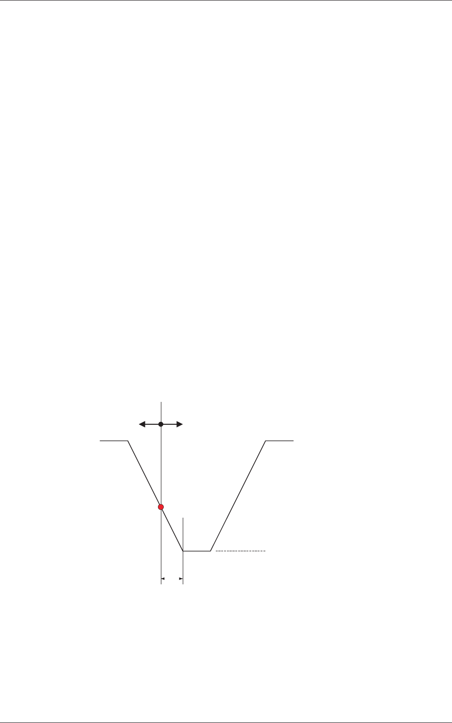
10ms
(+)(-)
NL-Axis Bottom Arrival Point
Vacuum ON/OFF Timing Reference
NL-Axis Descending NL-Axis Ascending
Fig. 3F29
0606-009
2.1 Device Offset Data

6-31
AIVEDT-ID
[3] Pu retention time [sec]
Set a parameter to specify the time when the nozzle must be stopped at
the lower limit for all component picks.
Note
Use this function when components cannot be picked up in stable condition
due to the influence of the component pickup surface and the compatibility
with the selected nozzle.
[4] Pl retention time [sec]
Set a parameter to specify the time when the nozzle must be stopped at
the lower limit for placement of all components.
0606-009
2.1 Device Offset Data
6-32
AIVEDT-ID
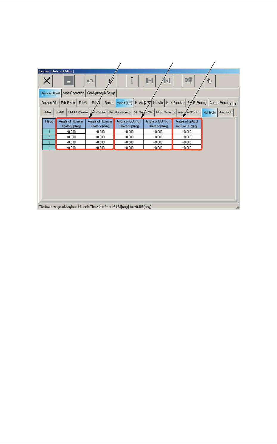
2.1.13 Head Inclination Offset
When the "Head [1/2]" tab is pressed in the "Device Offset" tab sheet and the
"Hd. Incln" tab is selected, the following tab sheet appears.
[1] [2]
[3]
Fig. 3F30 "Head Incln" Tab Sheet
Head 1, Head 2, Head 3, and Head 4
[1] Angle of HL incln Theta X [deg], Theta
Y [deg]
The set parameter is used to correct the deviations in the X and Y
direction that will be caused while the HL-axis is moving down if the
axis is tilted.
[2]
Angle of DD incln Theta X [deg], Theta Y
[deg]
The set parameter is used to correct the deviations in the X and Y
direction that will be caused while the HL-axis is moving down if the
DD-axis is tilted.
[3] Angle of optical axis incln [deg]
The set parameter is used to correct the angle of the component
recognition camera shot.
2.1 Device Offset Data
0606-009