3OM-1208-011_w.pdf - 第282页
6-49 AIVEDT -ID Z (Angle) [deg] Set the parameters representing the angular deviations in the scanning coordinates of the component recognition cameras based on the machine reference X/Y coordinates (Xm-Ym). When the cam…
6-48
AIVEDT-ID
Set the following offset values for each camera.
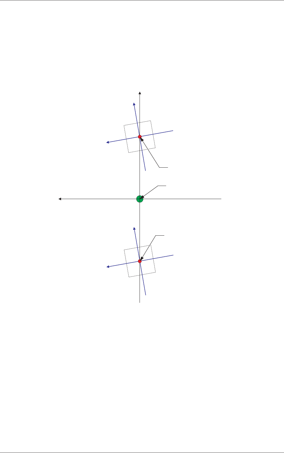
[1] Comp Recog Camera
X (Horizontal) and Y (Vertical) [mm]
The set parameters are used to adjust the positional deviations based on
the design dimensions between the machine reference coordinate origin
and the center of the component recognition cameras.
Xm (+)
Ym (+)
Xm-Ym : Machine Reference
Coordinate System
Xc-Yc : Component Recognition
Camera Coordinate System
Xc (+)
Yc (+)
Xc (+)
Yc (+)
Center of Component
Recognition Camera
Center of Component
Recognition Camera
Pm. Machine Reference
Coordinate Origin
Fig. 3F48
0606-009
2.1 Device Offset Data
6-49
AIVEDT-ID
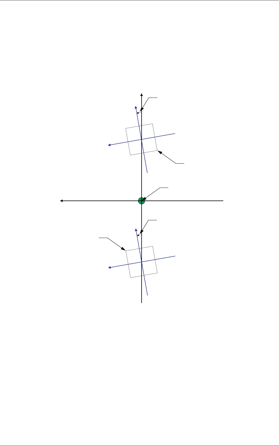
Z (Angle) [deg]
Set the parameters representing the angular deviations in the scanning
coordinates of the component recognition cameras based on the
machine reference X/Y coordinates (Xm-Ym).
When the camera scanning coordinates are shifted counterclockwise
to the machine reference X/Y coordinate system, a plus sign must be
affixed to each offset data.
Xm(+)
Ym(+)
Xc-Yc : Component Recognition
Camera Coordinate System
Xc (+)
Yc (+)
Xc (+)
Yc (+)
Pm. Machine Reference
Coordinate Origin
Angle of Component Recognition Camera
Angle of Component Recognition Camera
Component Recognition Camera
Component Recognition
Camera
Xm-Ym : Machine Reference
Coordinate System
Fig. 3F49
Magnification X (Horizontal) and Y (Vertical) [0.01 mm/pixel]
Set how many micrometers should be equivalent to one pixel to specify
the magnifi
cation of the component recognition camera.
The parameters are automatically calculated through teaching
operations performed using the magnification measurement jig.
•
Default:
6060
0606-009
2.1 Device Offset Data

6-50
AIVEDT-ID
0606-009
Contrast and Brightness
The brightness of the image captured by the component recognition
camera can be adjusted.
•
Default
Contrast :
102
Brightness
: 128
Note
(a) The larger the value for "Contrast" is, the stronger the chromaticness
becomes.
(b) The larger the value for "Brightness" is, the brighter the whole view
becomes.
[2] Comp Recog Brightness
Back, Front Lighting 1 (Ring (Dn)), Front Lighting 2 (Coax), Front
Lighting 3 (Ring (Up)),
Front Lighting 1+2 (Ring (Dn)+Coax), Front Lighting 1+3 (Ring
(Dn)+Ring (Up)), Front Lighting 2+3 (Coax+Ring (Up)), Front
Lighting 1+2+3 (Ring (Dn)+Coax+Ring (Up))
Set the brightness level for component recognition lighting.
•
Default
Back : 128
Front Lighting 1 (Ring (Dn)) :
160
Front Lighting 2 (Coax) : 160
Front Lighting 3 (Ring (Up)) : 128
Front Lighting 1+2 (Ring (Dn)+Coax) : 160
Front Lighting 1+3 (Ring (Dn)+Ring (Up)) : 0
Front Lighting 2+3 (Coax+Ring (Up)) : 160
Front Lighting 1+2+3 (Ring (Dn)+Coax+Ring (Up)) : 0
[3] Fly Recognition XY
X (Horizontal) and Y (Vertical) [mm]
Obtain the deflections (caused mainly due to the delay time of the
servoamplifier and the strobe) of the images captured by the stopped
component recognition camera (still image capture) and the flying
component recognition camera (fly image capture) and set the obtained
values to adjust the deviations in timing for image capture.
The set parameters are used to prevent a component from getting
af
fected by the delay and staying out of camera field of view.
2.1 Device Offset Data