3OM-1208-011_w.pdf - 第284页
6-51 AIVEDT -ID 2.1.24 T able Offset When the "T able" tab is pressed in the "Device Of fset" tab sheet and the "Head #1" tab is selected, the following tab sheet appears. Note As for the &q…

6-50
AIVEDT-ID
0606-009
Contrast and Brightness
The brightness of the image captured by the component recognition
camera can be adjusted.
•
Default
Contrast :
102
Brightness
: 128
Note
(a) The larger the value for "Contrast" is, the stronger the chromaticness
becomes.
(b) The larger the value for "Brightness" is, the brighter the whole view
becomes.
[2] Comp Recog Brightness
Back, Front Lighting 1 (Ring (Dn)), Front Lighting 2 (Coax), Front
Lighting 3 (Ring (Up)),
Front Lighting 1+2 (Ring (Dn)+Coax), Front Lighting 1+3 (Ring
(Dn)+Ring (Up)), Front Lighting 2+3 (Coax+Ring (Up)), Front
Lighting 1+2+3 (Ring (Dn)+Coax+Ring (Up))
Set the brightness level for component recognition lighting.
•
Default
Back : 128
Front Lighting 1 (Ring (Dn)) :
160
Front Lighting 2 (Coax) : 160
Front Lighting 3 (Ring (Up)) : 128
Front Lighting 1+2 (Ring (Dn)+Coax) : 160
Front Lighting 1+3 (Ring (Dn)+Ring (Up)) : 0
Front Lighting 2+3 (Coax+Ring (Up)) : 160
Front Lighting 1+2+3 (Ring (Dn)+Coax+Ring (Up)) : 0
[3] Fly Recognition XY
X (Horizontal) and Y (Vertical) [mm]
Obtain the deflections (caused mainly due to the delay time of the
servoamplifier and the strobe) of the images captured by the stopped
component recognition camera (still image capture) and the flying
component recognition camera (fly image capture) and set the obtained
values to adjust the deviations in timing for image capture.
The set parameters are used to prevent a component from getting
af
fected by the delay and staying out of camera field of view.
2.1 Device Offset Data
6-51
AIVEDT-ID
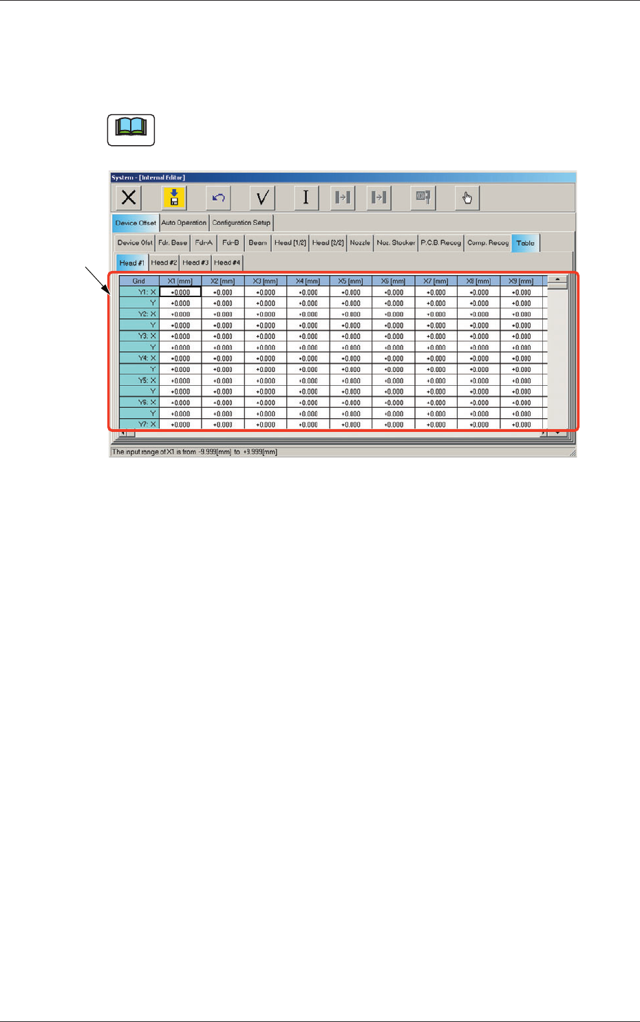
2.1.24 Table Offset
When the "Table" tab is pressed in the "Device Offset" tab sheet and the
"Head #1" tab is selected, the following tab sheet appears.
Note
As for the "Head #2", "Head #3", and "Head #4" tab sheets, the same
contents as the "Head #1" tab sheet are displayed.
[1]
Fig. 3F50 "Head #1" Tab Sheet
[1] Grid (X1 through X30, Y1 through Y30: X, Y) [mm]
Enter the amount of deviation based on the specified distance when
Head #1 has moved as far as the specified distance (each grid point,
X Direction: X1 through X30, Y Direction: Y1 through Y30) from the
PCB positioning reference.
These values are calculated automatically through the teaching
operation and entered in each text box.
0606-009
2.1 Device Offset Data
6-52
AIVEDT-ID
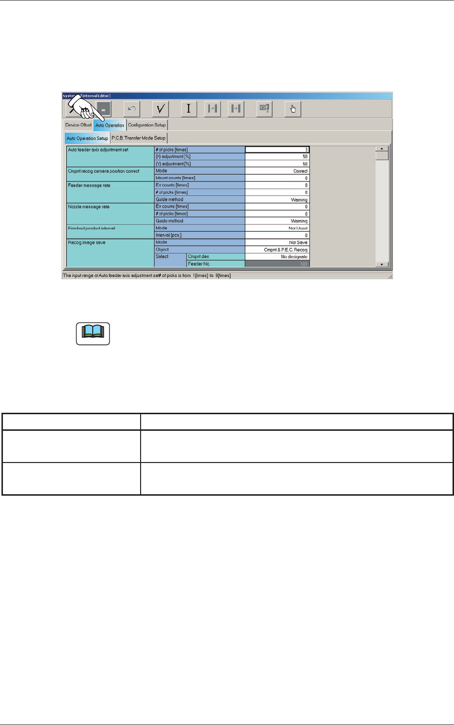
2.2 Auto Operation
When the "Auto Operation" tab is pressed in the "System - [Internal Editor]"
window, the following tab sheet appears.
Fig. 3F51 "Auto Operation" Tab Sheet
Note
The tab sheet may look different, depending on which options are selected.
The "Auto Operation" tab sheet has the following subtab sheets. When a
subtab is pressed, the corresponding subtab sheet appears.
Table 3F4
Tabs Description
Auto Operation Setup
Set various types of parameters related to the automatic operation of
the machine.
PCB Transfer Mode Setup
Set the operation mode of the input and output machines and the
requirements for PCB transfer and positioning operations.
0606-009
2.2 Auto Operation