3OM-1208-011_w.pdf - 第299页
6-66 AIVEDT -ID [9] Input conveyor T imer #1 [sec] Set the time to limit the operating time (PCB reception from the input machine) of the input conveyor . This timer measures the operating time of the input conveyor and …

6-65
AIVEDT-ID
[8] Output Setup
Output mode
Select "Standard", "Interval", or "SMEMA" to determine how to
transfer PCBs from the main machine to the output machine.
Standard
When the output machine is manufactured by us, set "Standard" in
the text box.
When the work request signal is received from the output machine,
the PCB transfer signal of the machine is turned ON and a PCB is
transferred to the output machine by the output conveyor
.
When the work request signal is not turned OFF within the specified
time after a PCB unloading action has started, the machine stops in
an error condition.
Interval
When the work request signal of the output machine is turned ON,
PCBs on the machine side are transferred to the output machine.
The conveyor stops when the output conveyor timer 1 has reached
the specifi
ed time.
The machine starts its unloading actions when the unloading
condition is fulfilled after the conveyor has stopped running and
the time specified in the "Output interval timer [sec]" text box has
elapsed.
Note
No error detection is made.
SMEMA
PCBs are transferred according to the "SMEMA" standard.
Output interval timer [sec]
When "Interval" is set in the "Output mode" text box, set the time as
interval time for PCB unloading actions.
PCB delivery Position [mm]
Set the position where PCBs are received.
T
ransfer speed [mm/sec]
Set the PCB transfer speed.
•
Default:
300 [mm/sec]
Note
When the unloading system of the output machine is used in a
mode other than the standard one and the PCB transfer speed of
the output machine is slow, the transfer speed must be adjusted
to one on the output machine side.
A PCB may be trapped during the arrangement of the conveyor
Y position.
2.2 Auto Operation
0606-009

6-66
AIVEDT-ID
[9] Input conveyor
Timer #1 [sec]
Set the time to limit the operating time (PCB reception from the input
machine) of the input conveyor
.
This timer measures the operating time of the input conveyor and is
used to detect an interrupted PCB.
Add 2 seconds (approx.) to the time required for PCB reception from
the input machine and set the time in the text box.
Note
Add 2 seconds (approx.) to the time required for PCB reception from the input
machine and set the time in the text box.
[10] PCB locate
Stopper setup
"Enable" or "Disable" can be selected to determine whether or not the
PCB positioning stopper should be used for the PCB positioning.
"Enable"
:
The PCB positioning stopper is used.
"Disable" :
The PCB positioning stopper is not used.
[1
1] Output conveyor
Timer #1 [sec]
Set the time to limit the operating time (PCB reception by the output
machine) of the output conveyor.
Note
Add 2 seconds (approx.) to the time required for PCB reception by the output
machine and set the time in the text box.
2.2 Auto Operation
0606-009
6-67
AIVEDT-ID
0606-009
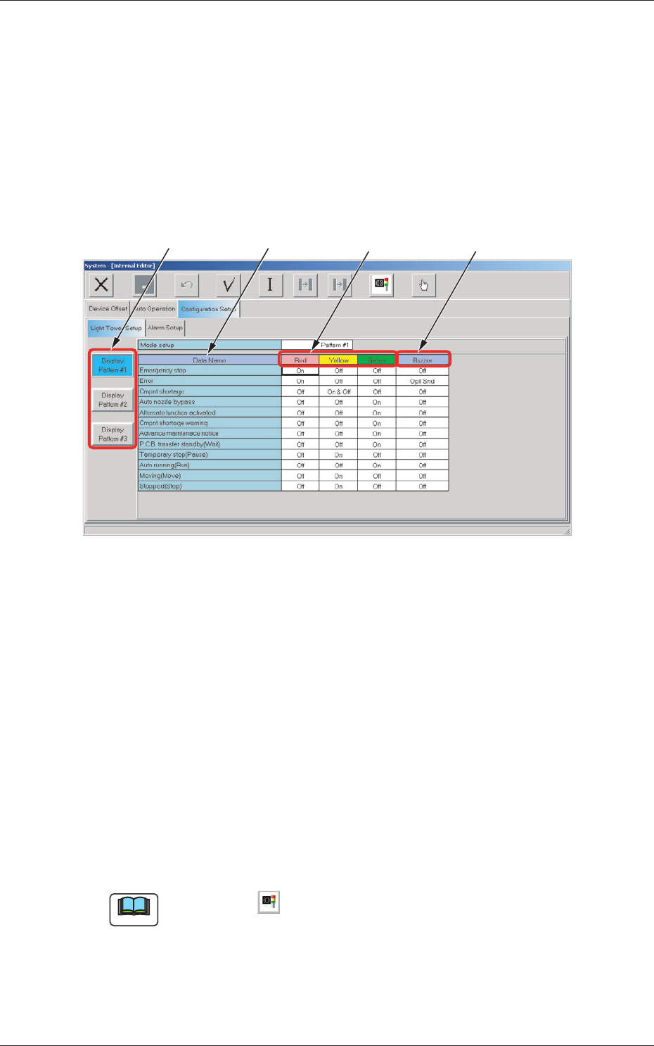
2.3 Configuration Setup Data
2.3.1 Light Tower Setup
The corresponding tab sheet enables the operator to allocate the lamp colors
for the light tower and the buzzer sounds.
When the "Light Tower Setup" tab is pressed in the "Configuration Setup"
tab sheet, the following tab sheet appears.
[4]
[2] [3]
[1]
Fig. 3F57 "Light Tower Setup" Tab Sheet
[1] Data Name
Displayed are the items for which the colors (red, yellow, and green) of
the tower lights and the types of alarm sounds should be specified.
[2] Red, Yellow, Green
Set "ON", "ON AND OFF", or "OFF" for the tower lights (red, yellow,
and green).
[3]
Buzzer
Set "Off", "Intmt Snd", "Cont Snd", or "Optl Snd" in each text box to
specify the types of alarm sounds.
The desired sound patterns can be made, using the "Alarm Setup" tab
sheet.
Note
When the icon ( ) is pressed, the standard settings (defaults) resume.
2.3 Configuration Setup Data