3OM-1208-011_w.pdf - 第66页
1-7 AIVEDT -ID 2.3 Composition of Placement Head/Nozzle Data This data is used to allocate the nozzles to the specified positions (Nozzle Allocation Nos.) on the heads. Set the IDs of the nozzles to be allocated for each …
1-6
AIVEDT-ID
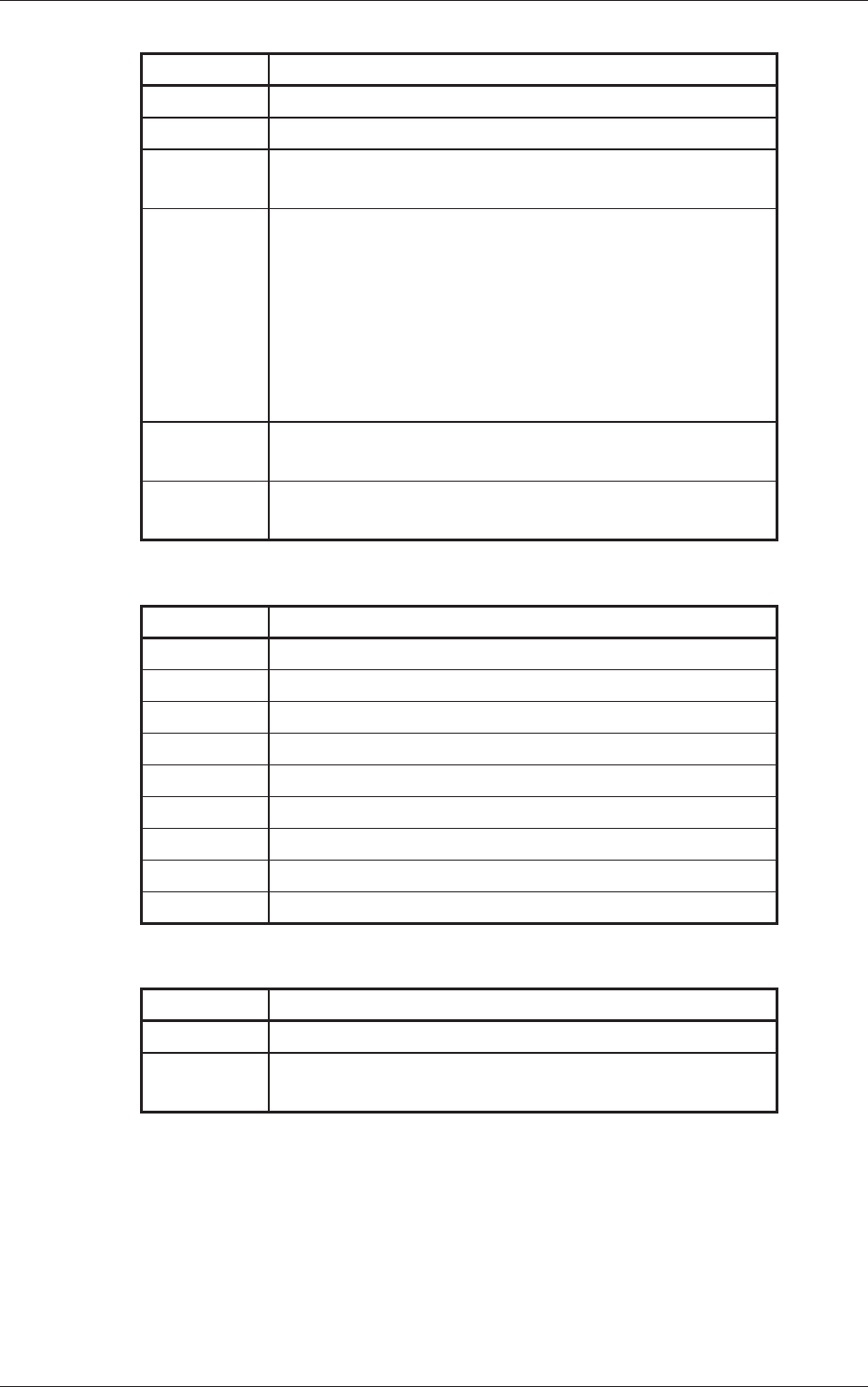
A02 PEC Recognition Data Table 3A2
Ref. No. Data Name
A02_01 PEC recognition function
A02_02 Correction algorithm
A02_03 PEC recognition Mode
Global (Zones 1 through 5), Image, local
A02_04 Fiducial mark (Zones 1 through 5)
#1 X (Horizontal), Y (Vertical) [mm],
Mark Code
#2 X (Horizontal), Y
(Vertical) [mm],
Mark Code
#3 X (Horizontal), Y (Vertical) [mm],
Mark Code
A02_05 Beam
Stage 1 and Stage 2
A02_06 Sequence
Stage 1 and Stage 2
A03 PEC Recognition Mark Data T
able 3A3
Ref. No. Data Name
A03_01 Mark No.
A03_02 Mark Type
A03_03 Mark Size D1 [mm], D2 [mm]
A03_04 Angle [deg]
A03_05
Window Size [mm]
A03_06 Mark Image
A03_07 Mark Level
A03_08 Lighting Level Coax
A03_09 Lighting Level Ring
A04 Setup Data T
able 3A4
Ref. No. Data Name
A04_01 Conveyor
A04_02 PCB Y Position Arrangement
Mode, Specify Method, Position [mm]
2.2 Composition of Operation Data
0606-009

1-7
AIVEDT-ID
2.3 Composition of Placement Head/Nozzle Data
This data is used to allocate the nozzles to the specified positions (Nozzle
Allocation Nos.) on the heads.
Set the IDs of the nozzles to be allocated for each individual heads.
Reference
Refer to "1.3 Placement Head/Nozzle Data" in "Chapter 3" for the details
of each item.
B01 Placement Head/Nozzle Table 3A5
Ref. No. Data Name
B01_01 Head 1, 2, 3, and 4
Nozzle 1 through 12, ID Names
2.3 Composition of Placement Head/Nozzle Data
0606-009
1-8
AIVEDT-ID
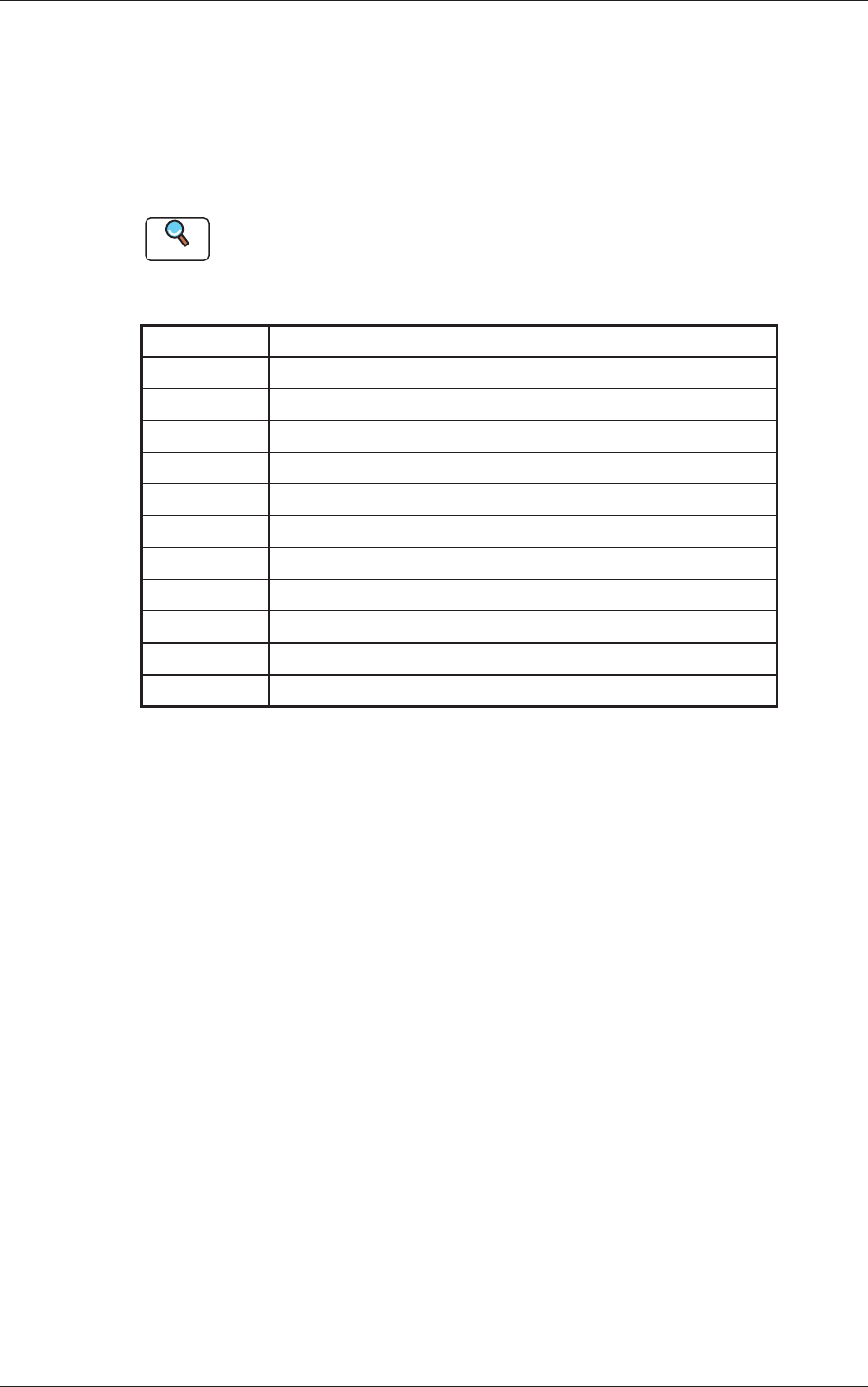
2.4 Composition of Placement Feeder Location Data
The set parameters are used to determine which feeder slot Nos. (Fdr No.)
various types of components should be allocated to.
Component IDs (types of components to be allocated) must be specified for
each individual feeder bases.
Reference
Refer to "1.4 Placement Feeder Location Data" in "Chapter 3" for the
details of each item according to the reference Nos. (Ref. Nos.).
C01 Feeder Bases #1, #2, #3, #4, and Work Area Table 3A6
Ref. No. Data Name
C01_01 Fdr No.
C01_02 Component ID
C01_03 C (Control Command)
C01_04 Comment
C01_05 Feeder Fixed
C01_06 Feeder
Alternate
C01_07 Fdr No.
C01_08 Component Library Comment
C01_09 Dir [deg], Carrier Data
T
ype, Width [mm]
C01_10 Fd. Pitch [mm]
C01_11
Used Parts
2.4 Composition of Placement Feeder Location Data
0606-009