3OM-1208-011_w.pdf - 第97页
3-10 AIVEDT -ID 0606-009 (A01_08) Pre-Placed component thickness T op [mm] When some components are placed previously on a PCB by the input machine, etc., and transferred to the main machine, be sure to enter the thickne…

3-9
AIVEDT-ID
(A01_06)
PCB locate Sequence
Select one of the following options as a PCB positioning sequence.
Standard :
Backup and Z Clamp Activated
Mode #1 :
Z Clamp Activated
(A01_07)
PCB transfer Sequence
Select one of the following options as a PCB transfer sequence.
Synchronous Priority :
PCBs are received and transferred at the same
time.
Output Priority
:
Priority is given to the PCB transfer after
component placement.
0606-009
1.2 Operation Data
3-10
AIVEDT-ID
0606-009
(A01_08)
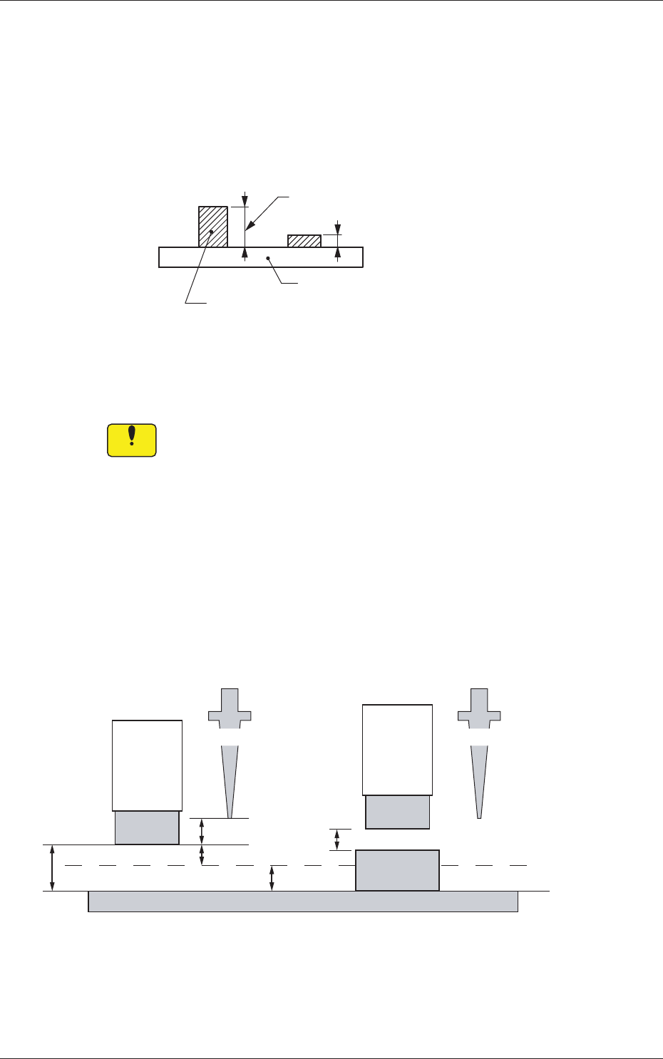
Pre-Placed component thickness
Top [mm]
When some components are placed previously on a PCB by the input
machine, etc., and transferred to the main machine, be sure to enter the
thickness of the tallest component of all in the text box.
Tallest Previously-Placed Component
Set this thickness in the text box.
PCB
Fig. 3C12
•
Data Input Range
0 to 12.700
Notice
(a) When components are placed previously and the main machine
is operated with
"
0.00
"
in this text box, some of the previously-
placed components may interfere with components to be
placed newly.
(b) It is advisable that placement data should be created such that
shorter components are placed before the tallest one.
(c) When the specified thickness of a previously-placed
component differs from the actual one, the light emitter of the
linear measure sensor may interfere with the previously-placed
component.
3.0 mm
5.0 mm
2.0 mm
3.0 mm
2.0 mm
No Previously-Placed Component
Previously-Placed Component
NL Origin Position NL Origin Position
Light
Emitter
Light
Emitter
Previously-
Placed
Component
PCB
Placement Level
Fig. 3C13
1.2 Operation Data
3-11
AIVEDT-ID
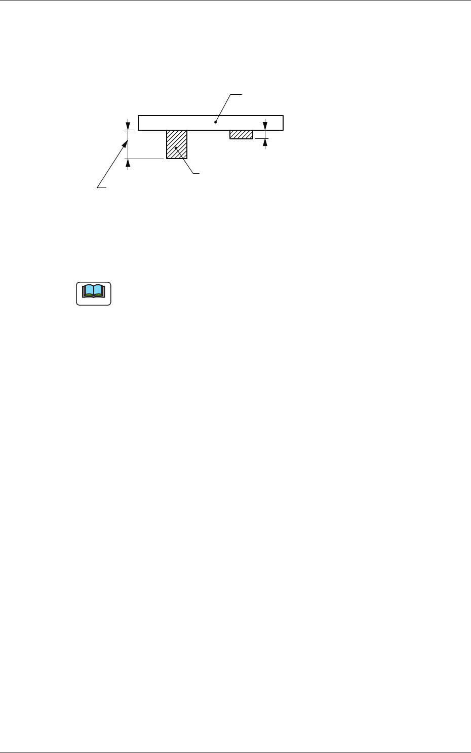
Bottom [mm]
When PCBs with some components already mounted on the lower
surfaces (back) by the input machine are transferred to this machine, be
sure to enter the thickness of the highest component in the text box.
Tallest Previously-Placed Component
PCB
Set this thickness in the text box.
Fig. 3C14
• Data Input Range
0 to 30.000
Note
(a) The set parameter is used to determine the position (elevation) of the
first backup table when the PCB is transferred to the PCB positioning
section.
(b) When components are placed previously and the main machine is
operated with "0.00" (no previously-placed components) in this text
box, the support pins may interfere with some of the previously-
placed components on the back of PCB while the PCB is being
transferred to the PCB positioning section.
(A01_09)
PCB transfer speed
Input, Between Stages, Output
Select one of the following options as PCB transfer speed.
Standard
:
PCBs are transferred at normal speed.
Low Speed 1 :
PCBs are transferred at a speed slower than
"
Standard
"
.
Low Speed 2 :
PCBs are transferred at a speed slower than
"
Low Speed 1
"
.
Low Speed 3 :
PCBs are transferred at a speed slower than
"
Low Speed 2
"
.
Specification Value :
Your desired speed can be specified.
0606-009
1.2 Operation Data