00193730-04.pdf - 第27页
Retrofit instructions Splice Detection Basic Packa ge + Table Controller SIPLACE HF-series 08/2005 Edition 27 2.7 Inst allation : Remove the communication inte rface by loosening the screws that fix th e devic e to the c…
Retrofit instructions Splice Detection Basic Package + Table Controller SIPLACE HF-series
08/2005 Edition
26
2.6 Preparation
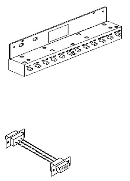
First familiarize yourself with the new hardware components to be installed, as shown in
Fig. 5 - 1. 2
2
Abb. 2.10 - 1 Retrofit kit "Splice detection for HF changeover table"
2
HF table controller (TC)
Part no.: 03006500-01
Adapter for power supply
Part no.: 03006409-01
Retrofit instructions Splice Detection Basic Package + Table Controller SIPLACE HF-series
08/2005 Edition
27
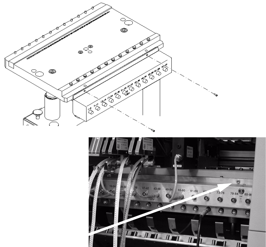
2.7 Installation
: Remove the communication interface by loosening the screws that fix the device to the chan-
geover table (Fig. 6 - 1), and unplugging the power and communication cables at the back.
2
Abb. 2.10 - 1 HF changeover table with communication interface
2
2
2
2
2
2
Retrofit instructions Splice Detection Basic Package + Table Controller SIPLACE HF-series
08/2005 Edition
28
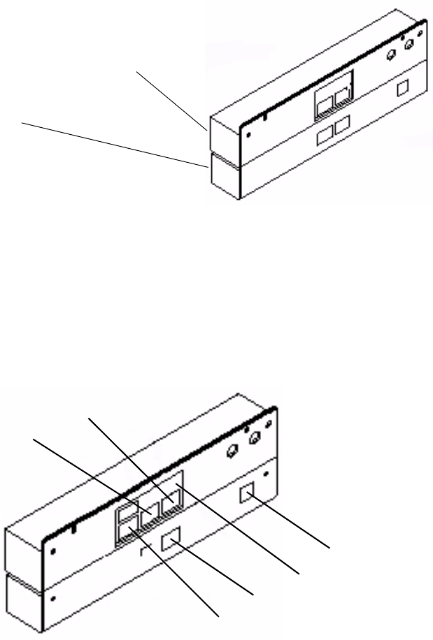
: Connect the communication interface and table controller (TC) to one another. The screws that
protrude from the communication interface should fit into the recesses in the table controller
case. If necessary, loosen the screws on the back of the table controller slightly (Fig. 6 - 2), fit
the communication interface and then tighten the screws once more.
2
Abb. 2.10 - 2 Communication interface and table controller (TC) connected to one another
: Plug in and secure the connectors that you removed when dismantling the communication in-
terface (Fig. 6 - 3).
: Plug the communication connector (9-pin) into socket #1 and the power supply connector (3-
pin) into socket #3. Screw the green/yellow grounding cable to the back panel of the TC using
a hexagon socket head screw.
2
Abb. 2.10 - 3 Whole unit showing the connector and ground positions
2
2
2
Communication unit
TC
#5
GND
#4
#3
#2
#1