TR7500E_Manual_en_v28 - 第135页
C h a p t e r 3 A O I A T P G F u n c t i o n i n s t r u c t i on T R 7500 U S E R M A N U AL 1 28 2 . Ed it Co m po n e nt Da t a l M a i n f r a m e f o r e d i t i n g c o m p o n e n t d a t a . T h e m ea n i n g s…
Chapter 3 AOI ATPG Function instruction
TR7500 USER MANUAL
127
(11) Translate – Start to translator CAD file to AOI file.
(12) Quit – Exiting the translator procedure.
1.3. Import
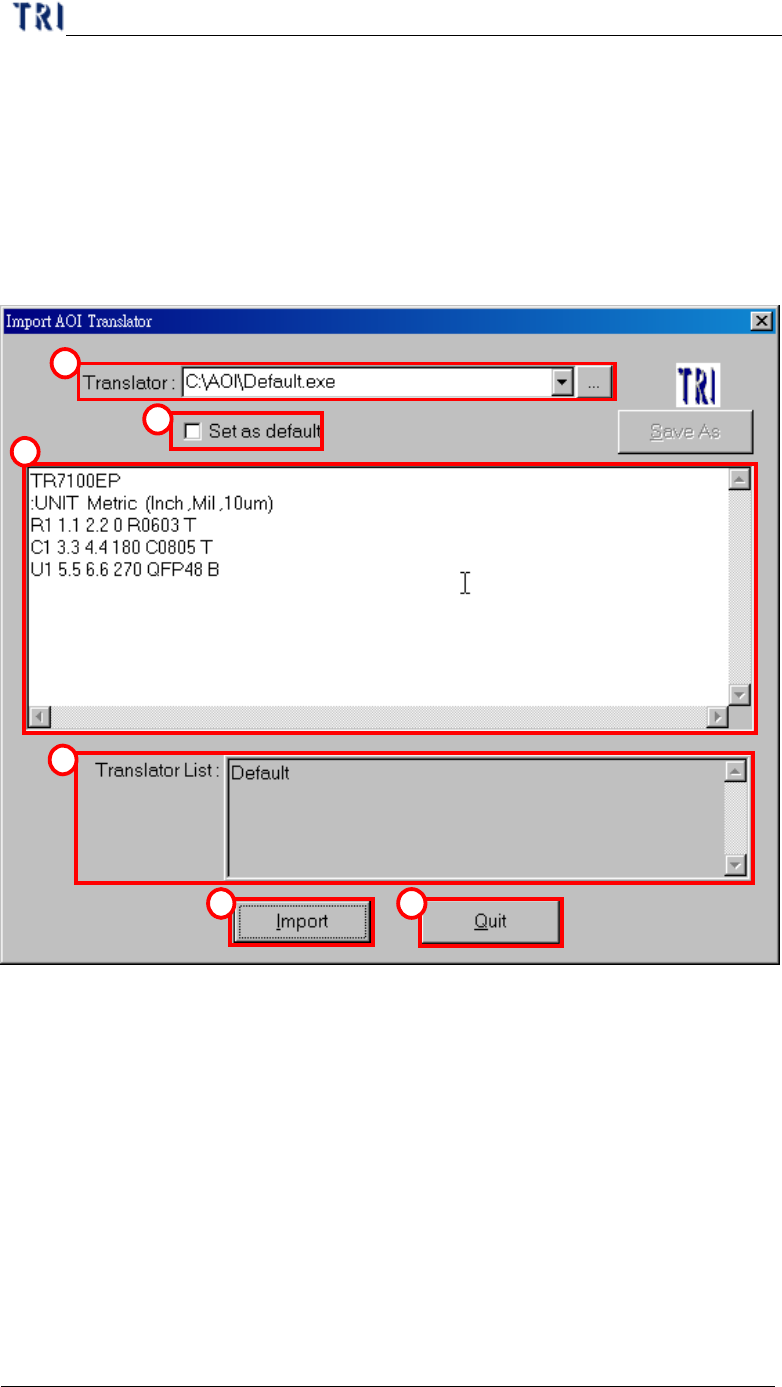
In section 1.2. , press “Import” in “File translator” dialog, then you will enter
“Import AOI Translator” dialog as the following.
1
2
3
4
5 6
(1) Translator – Input or add a new translator file.
(2) Set as default –Used current translator file as default.
(3) Message windows –Display the standard form of the translator for example.
(4) Translator list – All translator lists in the system.
(5) Import – Loading the new translator.
(6) Quit – Exiting translator import.
Chapter 3 AOI ATPG Function instruction
TR7500 USER MANUAL
128
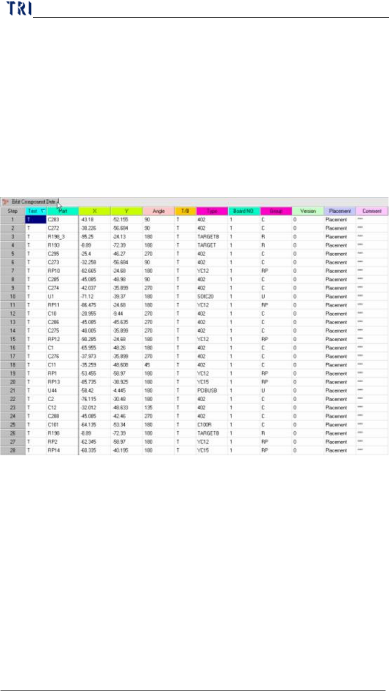
2. Edit Component Data
l Mainframe for editing component data. The meanings of all fields from left to
right are: test or not, component name, X coordinate, Y coordinate, component
angle, top or bottom side, component type, board number and group of the
component (the system separates the group automatically according to the
beginning characters of the component; you also can define the group manually
in the 7
th
field of AOI file.)
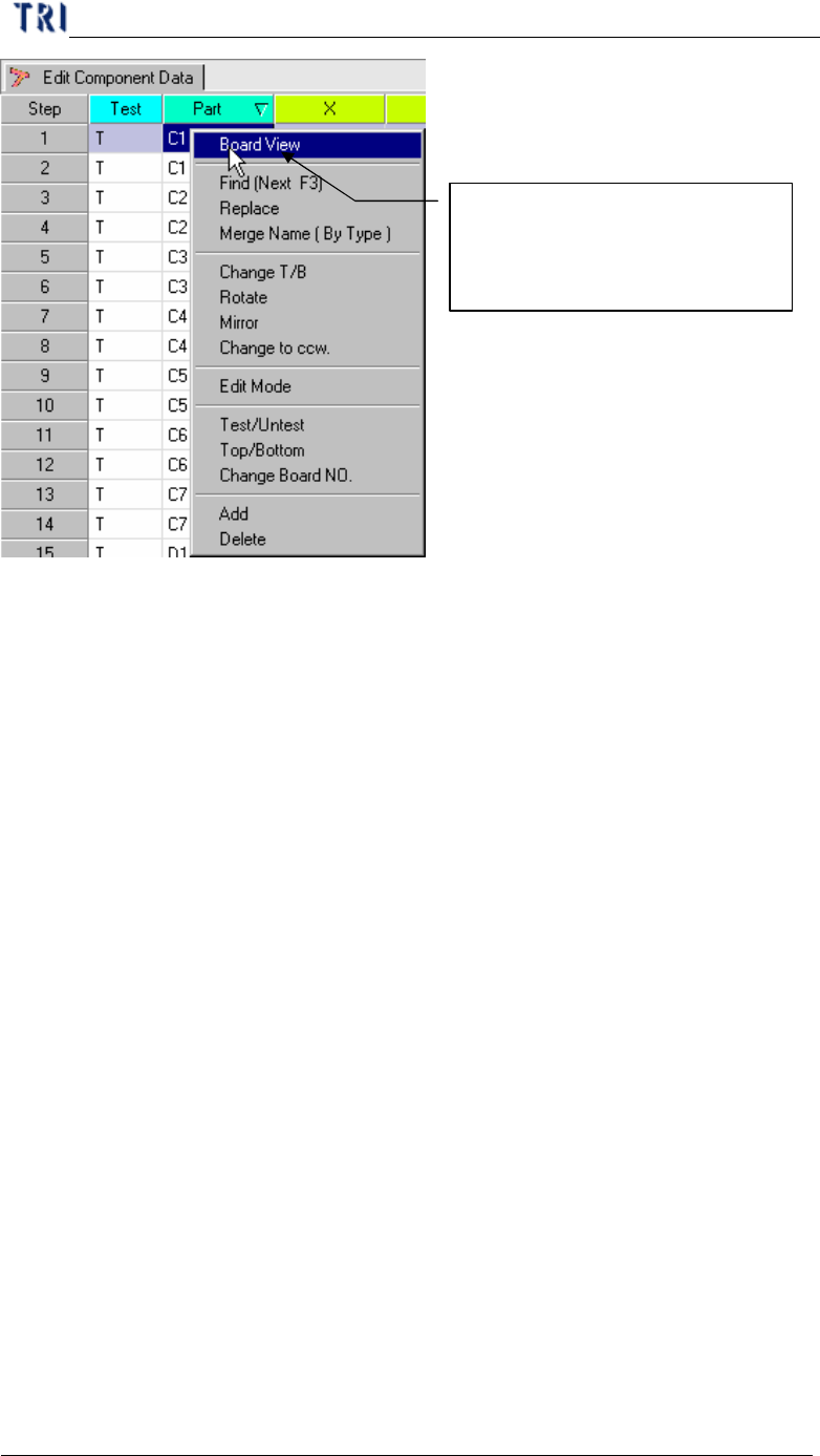
l When right clicking on the main frame, the pop-up menu will show. The
meanings of the tools will be explained later.
2.1. Board View
l Display the component position on the board from AOI file loading.
Chapter 3 AOI ATPG Function instruction
TR7500 USER MANUAL
129
l Display the component position data on the board.
Choosing the parts and clicking
the right button of mouse to
open the function menu.