TR7500E_Manual_en_v28 - 第178页
C h a p t e r 3 A O I A T P G F u n c t i o n i n s t r u c t i on T R 7500 U S E R M A N U AL 1 71 i n i t i a l p o s it i o n o f c l i c k i n g m u s t b e a t t h e s a m e s i d e w i t h I C p i n a g a i n s t b…
Chapter 3 AOI ATPG Function instruction
TR7500 USER MANUAL
170
Add body box by mouse drag
Add Pin box by mouse drag
Add inspection property box by mouse drag
Auto add inspection boxes
Auto add polarity pair inspection box
10.4.1. Body
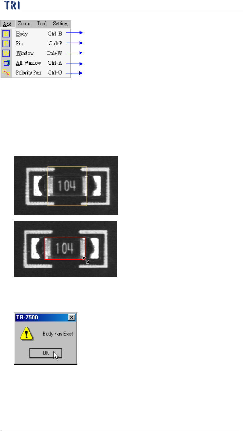
l The system will get the size and position of components by the body box.
Creating body box also can help for editing library.
l Press [Body] and system will create a yellow and square body box. You should
adjust the size of body box by clicking and dragging mouse and move the
position to the component center by [Motion Control] dialog.
l There is only one body window for one component. If the body has existed and
you also press [Body] the following window will be appeared. You should press
[OK].
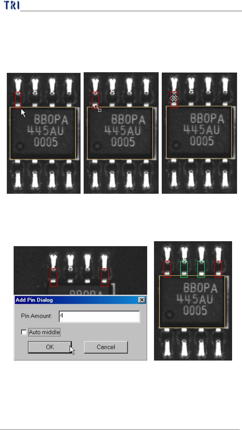
10.4.2. Pin
l The system will get the size, position and number of IC pins by the pin box.
Creating pin box also can help for editing library.
l You can click and drag by mouse to create a pin box after pressing [Pin]. The
Chapter 3 AOI ATPG Function instruction
TR7500 USER MANUAL
171
initial position of clicking must be at the same side with IC pin against body
window because system judges the position of IC pin by initial clicking. If you
create a pin at left side of body then move it to top side, the system will make
mistakes later.
l You can adjust the size and position to match the IC lead.
l If you select 2 pins and press [Pin], the following dialog will be appeared. You
can input total number of pins and press [OK]. The system will create the pins by
interpolation. When you check [Auto middle] the all pins will move against the
middle of body.
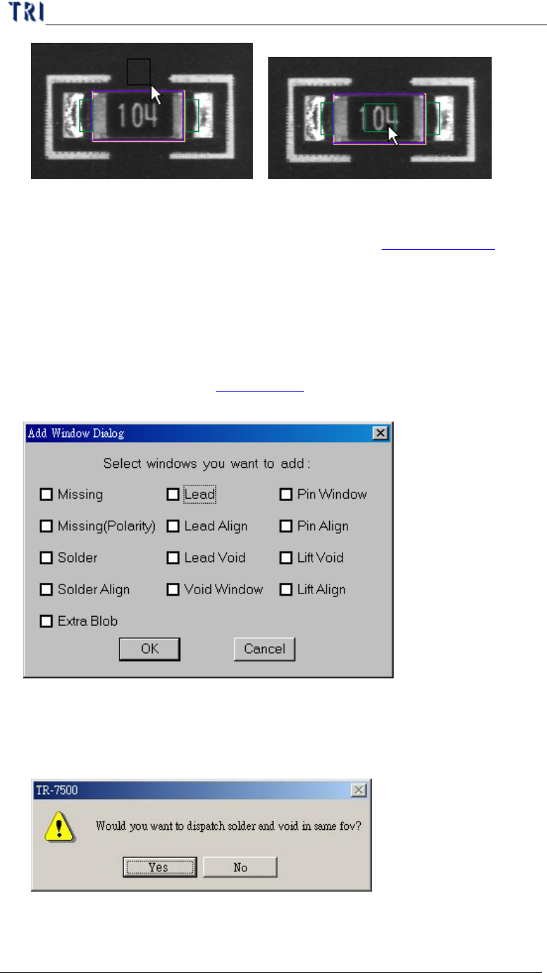
10.4.3. Window
l You can click and drag by mouse to create a pin box after pressing [Window].
Then move the window to correct position.
Chapter 3 AOI ATPG Function instruction
TR7500 USER MANUAL
172
l The defaults of window are [TopCamera], [Topsidelight] and [Void Window].
You can click on [Property] to change the settings (See Chapter 3 10.7.2. )
10.4.4. All Window
l Check windows that you need and the windows can create at the same time.
Missing and Missing(Polarity) are created on the body box. Solder, Lead, Lead
Void, Pin Window and Lift Void are created on the pin boxes. Align is created to
cover all pins. You can go to Chapter 3 11. To see the principle of inspection
window.
l When selecting [Solder] and [Void Window] at the same time and pressing [OK],
you can select whether you want to arrange Solder and Void windows at the same
FOV.
10.4.5. Polarity Pair