TR7500E_Manual_en_v28 - 第215页
C h a p t e r 3 A O I A T P G F u n c t i o n i n s t r u c t i on T R 7500 U S E R M A N U AL 2 08 ( 8) A d d i m a g e o f l e a d a n d s o l d e r i n s p e c ti o n wi n d o w . Al l i n s p ec t i o n wi n d o w s …
Chapter 3 AOI ATPG Function instruction
TR7500 USER MANUAL
207
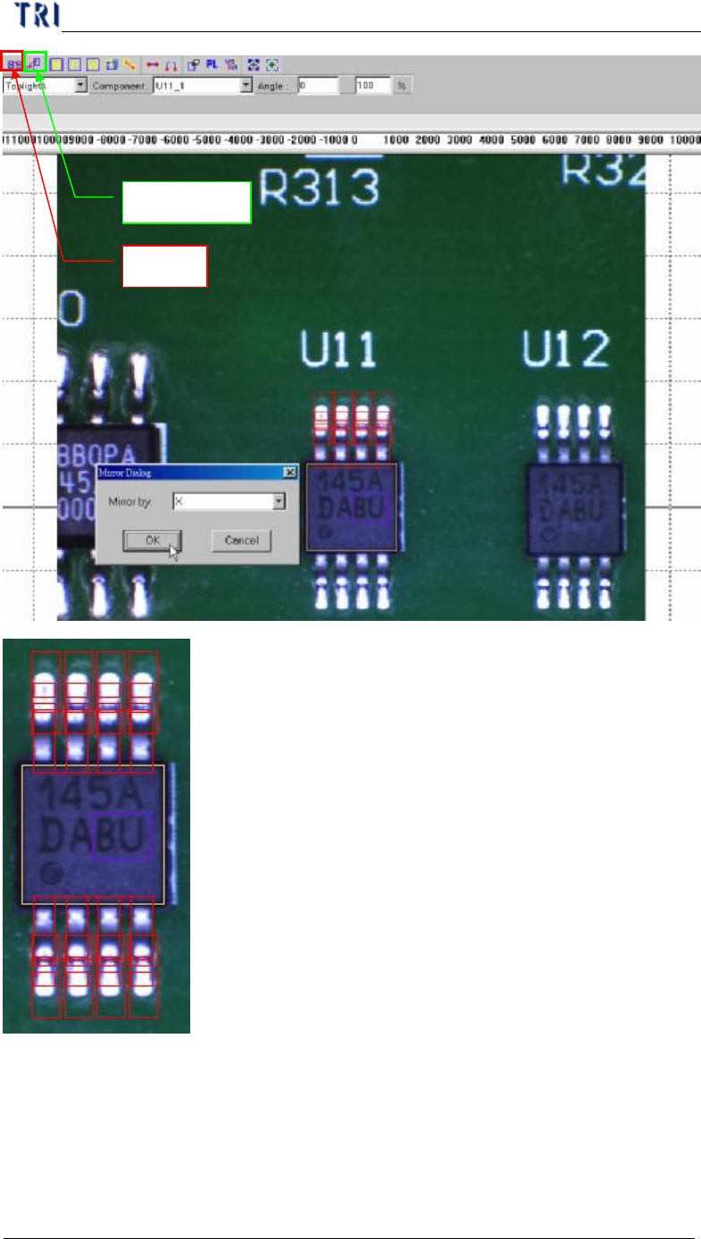
Mirror
Rotate Copy
Chapter 3 AOI ATPG Function instruction
TR7500 USER MANUAL
208
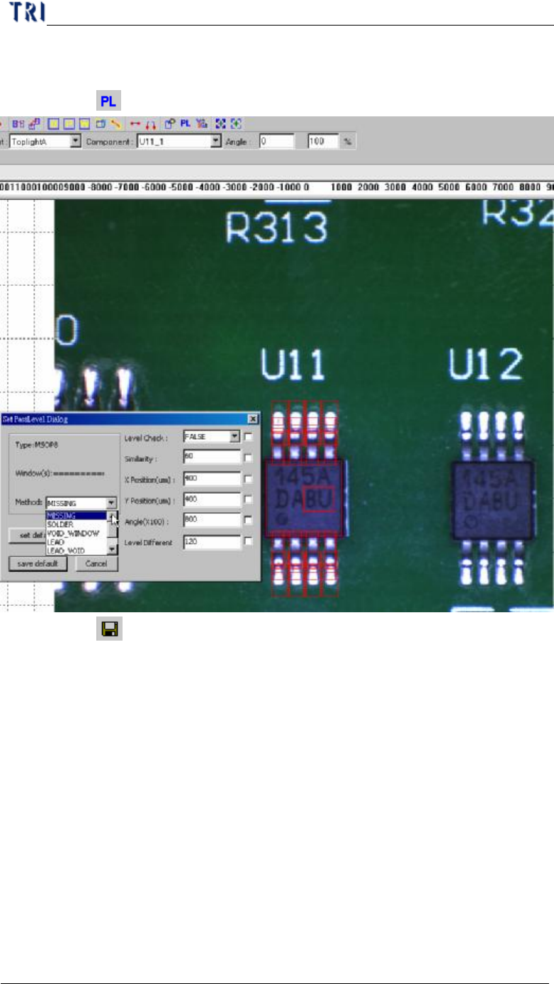
(8) Add image of lead and solder inspection window. All inspection windows with
the same method will use the image.
(9) Click on [ Pass Level] to set pass level for all types.
(10) Click on [ Save] to save this type. The system will store the saved file in
[C:\AOI\packagelibrary] folder
11. Principle and pass level setting
11.1. Method of Image Matching
11.1.1. Method 1– Geometric Feature Matching
l System saves the pattern and features of the image and inspects the image
according to the features. [Missing] is inspecting with this algorithm and you can
select this algorithm to do image matching for [Warp].
11.1.2. Method 2– Normalize Correlation Matching
l System learns gray level and feature of the image then finds the best matching
object in the search range when inspecting. [Lead] is inspecting with this
algorithm and you can select this algorithm to do image matching for [Warp].
Chapter 3 AOI ATPG Function instruction
TR7500 USER MANUAL
209
11.1.3. Method 3– Projection Profile Matching
l After projecting the gray level to the X and Y axis, system takes the projections
as the feature to inspecting. [Align] is inspecting with this algorithm.
11.2. Principle and Setting
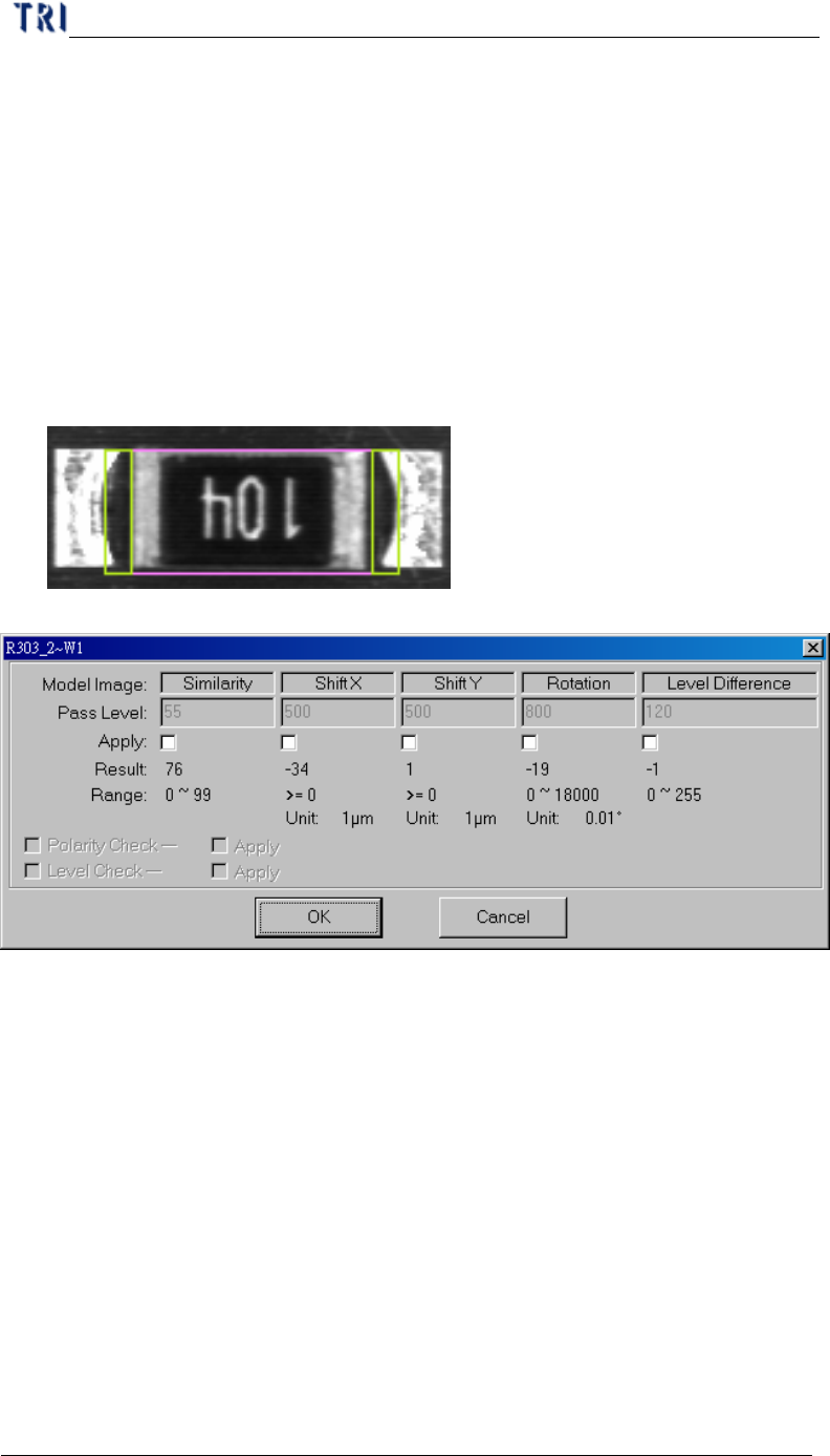
11.2.1. Model image (Missing/Missing Polarity)
l To check the missing, shift, tombstone and polarity of components. Use Pattern
Match Method (Method 1); grab a good image model for sample. Compare with
test component to Find the defect
l Pass level setting
n Similarity – The similarity between standard image and inspected image.
n Shift X – The tolerance of shift on x direction.
n Shift Y – The tolerance of shift on y direction.
n Rotation – The tolerance of rotate angle
n Level difference – System will save the gray level average of 10x10 pixel
area at the center of box for inspecting. For example, if the trained value is
100 and the level difference tolerance is 35. It means the system will show
fail when the result is over 135 or less than 65.
n Polarity Check – If the component rotates 180 degrees will be judged as a
defect.
n Level Check – Select to open the [Level Difference] function.
11.2.2. Lead