TR7500E_Manual_en_v28 - 第22页
C h a p t e r 1 AO I S t a nd a r d P r o j ec t Cr ea t i on T R 7500 U S E R M A N U AL 15 l C a m e r a mo v e m e n t c o n t r o l . ( S e e S e c ti o n C h a p t e r 3 3 . 3 . ) ( 7) G e tti n g t h e c o mp o n e…
Chapter 1 AOI Standard Project Creation
TR7500 USER MANUAL
14
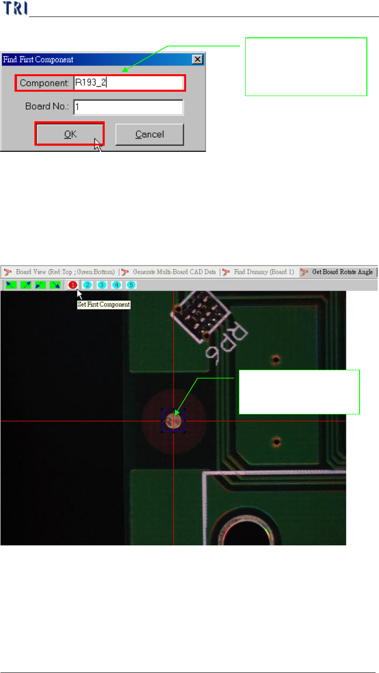
(5) Input reference component name.
(6) Moving camera to center of the component. You can use [Motion Control]
function to move camera to specific direction and distance or click right button
of mouse on image zone to move camera to the clicking position. You can adjust
the size of blue frame to suit the specific component. That you can find the
center easily.
Inputs the board first
component name for
position find
Moving camera to
center of the component
Chapter 1 AOI Standard Project Creation
TR7500 USER MANUAL
15
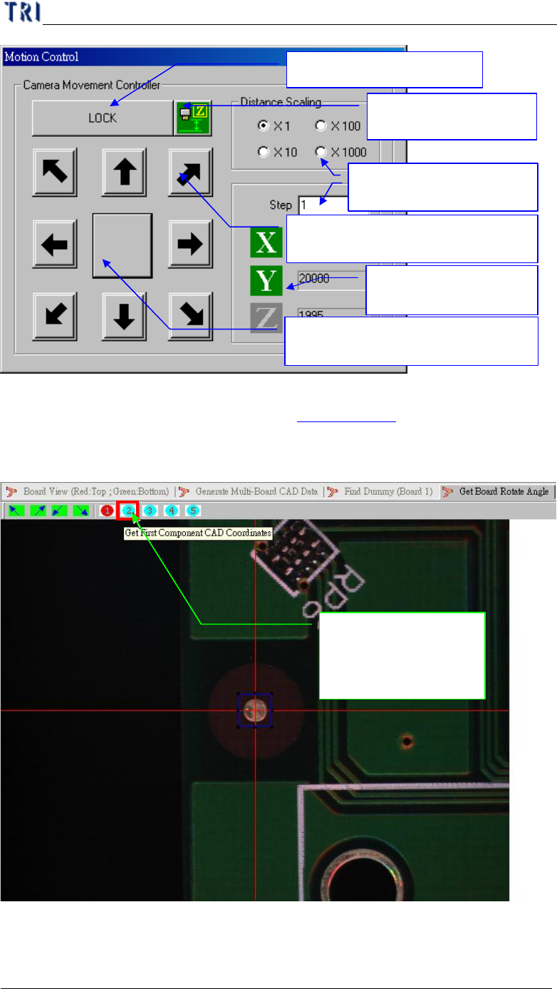
l Camera movement control. (See Section Chapter 3 3. 3. )
(7) Getting the component position in XY table.
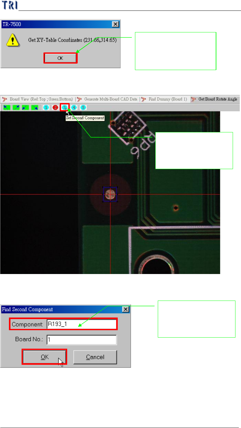
(8) Display get XY table coordinate.
Push the button and
record the component
position
Press the arrow buttons for moving
XY table to specific directions
Press the center buttons for
minimizing the motion control table
Lock table for safety
Input XY table moving
steps and choose scaling.
Display the
coordinates of cameras
Change to the Z axis
control panel
Chapter 1 AOI Standard Project Creation
TR7500 USER MANUAL
16
(9) Setting second component for angle detection.
(10) Input reference component name.
(11) Getting the component position in XY table.
System show the double
confirm message for
record the position
Inputs the board second
component name for
position find
Setting the board seco
nd
component position for
board angle detection