TR7500E_Manual_en_v28 - 第224页
C h a p t e r 3 A O I A T P G F u n c t i o n i n s t r u c t i on T R 7500 U S E R M A N U AL 2 17 l T a k e a S O P d e s i g n a t o r f o r i n s t a n c e , t h e i m a g e t o t h e l e f t w a s ca p t u r e d b y…
Chapter 3 AOI ATPG Function instruction
TR7500 USER MANUAL
216
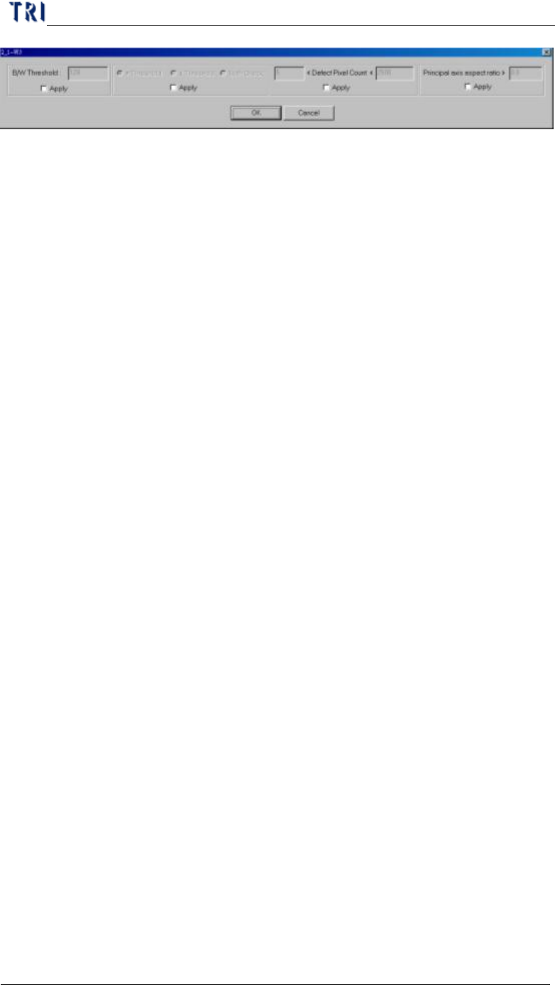
n B/W Threshold – Input the bright and white threshold
n >Threshold – Choosing this is to express that you only care about the pixel
which has greater gray level than threshold value and conforms to the
following conditions.
n <Threshold – Choosing this is to express that you only care about the pixel
which has greater gray level than threshold value and conforms with the
following conditions.
n Both – Choosing this is to express that you care about the pixel which has
greater or smaller gray level than threshold value and conforms to the
following conditions.
n <Defect Pixel Count< – The system marks the pixels that are not confirming
with threshold and regards neighborly marked pixels as a group. You can
input the minimum and maximum. When the size of a group is located in
the range, that group is regarded as a defeat. For example, you set “50<
Defect Pixel Count<500”. It means that the marked group is regarded as
defeat when the group size is between 50 to 500 pixels.
n Principal axis aspect ratio> –When the ratio of width to length of a defect
group is larger than the input value, the group will be regarded as a defeat.
The function can catch the white line which is appeared when an IC pin lifts.
You can input 0 when you do not want to use this function.
11.3. Color Check Method and RGB Weighting
11.3.1. Color Check Method
l The Top-View camera consists of three CCD light-sensors. Unlike the
monochromes, they tend to have much better contrast in images by regulating the
RGB Weighting. Inspection boxes that are particularly created using the top CCD
camera will have better quality sample images, and ready to set for comparison.
Hence, the camera can easily detect major contrasts on failing components; we
call it CCM (Color Check Method).
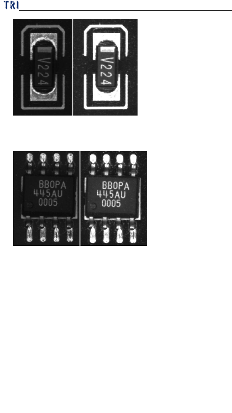
l Take a resistor chip for instance, the image to the left was captured by a
monochrome camera, and the image to the right was captured by a three color
sensor CCD camera and regulated by RGB Weighting.
Chapter 3 AOI ATPG Function instruction
TR7500 USER MANUAL
217
l Take a SOP designator for instance, the image to the left was captured by a
monochrome camera, and the image to the right was captured by a three color
sensor CCD camera and regulated by RGB Weighting.
l According to the previous examples, the surface shape and lighting angles on
solder joints may have great impact on the image quality. Therefore, images
that were captured by monochrome cameras having irregular gray scale level on
solder joints. Until now, images that were captured by three color sensor CCD
camera regulated by RGB Weighting reflect much better contrast which it gives
more stability on inspection boxes.
11.3.2. RGB Weighting Dialog
l We use percentage input for RGB Weighting parameter settings. By increasing
either R, G, or B setting would obtain desired contrast you wish for inspection
purposes. It can also eliminate unwanted color reflected by the boards for a
better accuracy of detection.
Chapter 3 AOI ATPG Function instruction
TR7500 USER MANUAL
218
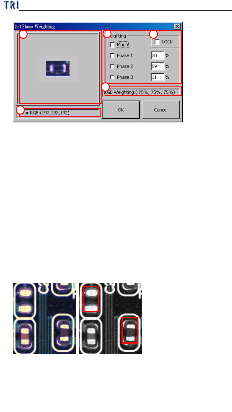
(1) Click on displayed image to zoom in.
(2) Displays RGB level value or the level value of Graylevel.
(3) Options and settings for RGB Weighting in percentage input.
(4) Check “LOCK” box to save the RGB setting as for the default settings.
However, “OK” button must be click to change the current RGB settings.
(5) Displays RGB Weighting in percentage ratio.
11.3.3. Example for 7500E RGB Weighting
l Take a missing designator for instance. The two figures below displayed in
color and monochrome. Within the monochrome figure, a placed designator
and missing designator locations are surrounded by red frames. The problem
with the missing designator location is that the software can easily mistaken by
having a similar base color compared to an actual placed designator’s body color.
The picture figure to the left is taken by TR7500E’s top true color CCD camera,
where the picture to the left was taken by a monochrome camera.
l The left figure below is showing that a missing designator has the gray level of
48, and a placed designator has the gray level of 60, which is very close to the
missing designator. This will cause unavoidable false calls or miss calls. These
pictures were captured by a monochrome camera, where the gray level is
1
3
4
2
5