TR7500E_Manual_en_v28 - 第226页
C h a p t e r 3 A O I A T P G F u n c t i o n i n s t r u c t i on T R 7500 U S E R M A N U AL 2 19 a n a l y ze d w it h i n t h e y e l l o w b o x . l T h e f o ll o wi ng p i c t u r e f i g u r e s a r e c a p t u r…
Chapter 3 AOI ATPG Function instruction
TR7500 USER MANUAL
218
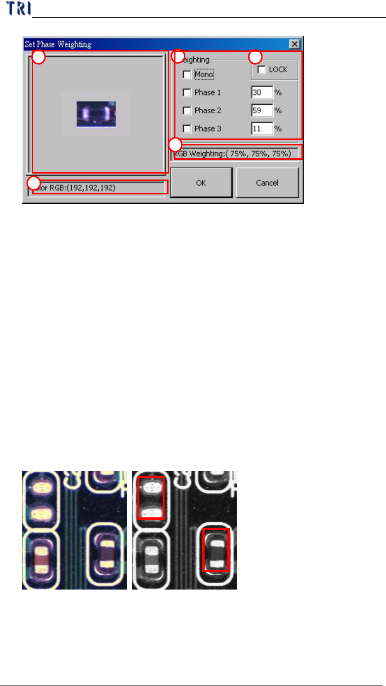
(1) Click on displayed image to zoom in.
(2) Displays RGB level value or the level value of Graylevel.
(3) Options and settings for RGB Weighting in percentage input.
(4) Check “LOCK” box to save the RGB setting as for the default settings.
However, “OK” button must be click to change the current RGB settings.
(5) Displays RGB Weighting in percentage ratio.
11.3.3. Example for 7500E RGB Weighting
l Take a missing designator for instance. The two figures below displayed in
color and monochrome. Within the monochrome figure, a placed designator
and missing designator locations are surrounded by red frames. The problem
with the missing designator location is that the software can easily mistaken by
having a similar base color compared to an actual placed designator’s body color.
The picture figure to the left is taken by TR7500E’s top true color CCD camera,
where the picture to the left was taken by a monochrome camera.
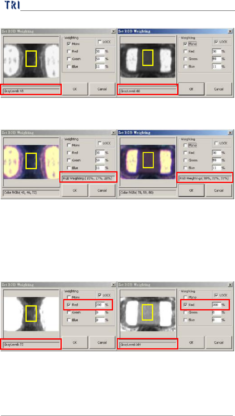
l The left figure below is showing that a missing designator has the gray level of
48, and a placed designator has the gray level of 60, which is very close to the
missing designator. This will cause unavoidable false calls or miss calls. These
pictures were captured by a monochrome camera, where the gray level is
1
3
4
2
5
Chapter 3 AOI ATPG Function instruction
TR7500 USER MANUAL
219
analyzed within the yellow box.
l The following picture figures are captured by the 3 CCD True Color Camera.
The RGB weighting ratios within the yellow boxes are: RGB(15%, 17%, 28%)
for a missing designator, and RGB(30%, ,22%, 31%) for a placed designator.
l According to the compared figures above, R makes the most value difference up
to twice as much. Therefore, we may now use the RGB Color Weighting to
make a better contrast between the two by raising R percentage ratio up to 200.
You may now see a much bigger gray level contrast between the two picture
figures below after leveling up the R ratio value and lowering down the B and
the G value.
l In general, the RGB Weighting function may reinforce the result of the color
reflection of components, making a better contrast during the inspection. RGB
Weighting method will tremendously reduce false calls and miss calls. Such
method we call it the “Color Check Method” (CCM).
Chapter 3 AOI ATPG Function instruction
TR7500 USER MANUAL
220
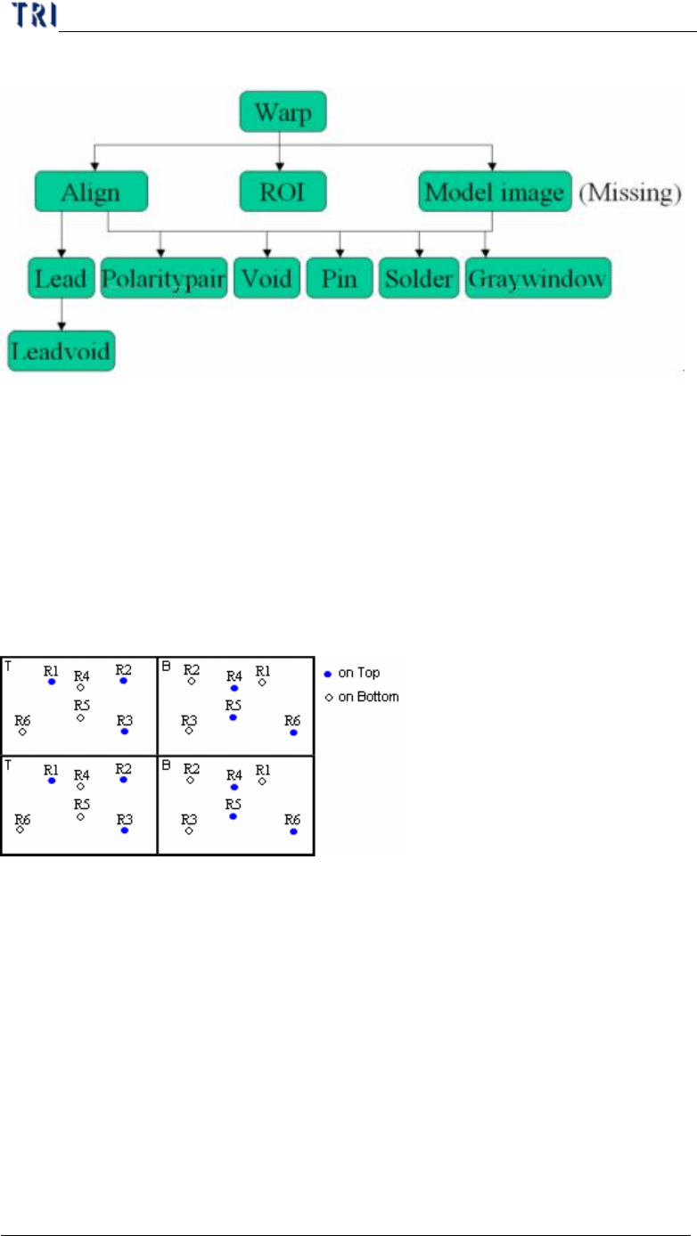
11.4. Structure of inspection boxes
l Inspection box lying in the upper strata can help to locate the inspection box in
the lower floor.
12. Principles for Top and Bottom of the Same Plane
12.1. CAD file arrangement
l The CAD must have both coordinates of top components and perspective
coordinates of bottom components.
12.2. Program Generating Procedure
Step1. Load CAD file.
Step2. [Edit component Data] – Edit the CAD data to make it displays correct
coordinates of top components and the perspective coordinates of bottom
components regarding Board 1.