00195193-02 SG D4 FSE en (1).pdf - 第104页
Communication and Control Reading the Board IDs out of the EEPROM Board type recognition Student Guide SIPLACE D4 (FSE) EN 09/2006 Communica tion and Control 103 4.4 - 13: Read the board type ID Head interface X (1) Rest…

Communication and Control
Board type recognition Reading the Board IDs out of the EEPROM
Student Guide SIPLACE D4 (FSE)
Communication and Control EN 09/2006
102
X To write the board IDs with CAN commands, make sure that just the BIOS is running on the TQM
module.
X Perform a BIOS download to the TQM module, so that you are sure that only the BIOS is running.
X Open the network 1 for PA 1 and network 2 to for PA 2.
X With the correct CAN ID and the BIOS commands, you can now write the correct board ID in the
EEPROM.
NOTE:
Always use the IDs which are shown in the subsystem control window, when
you click on the
GET VERSION or ACTIVATE IDs
button.
e.g. Head Processor
Gantry 1 -->
300
Gantry 2 -->
308
Gantry 3 -->
310
Gantry 4 -->
318
.
Exception: If you don‘t received a message from a subsystem, so you can try to
work with "Standard ID‘s" e.g.Head processor:
Gantry 1 -->
304
Gantry 2 -->
30c
Gantry 3 -->
314
Gantry 4 -->
31c
,
Required when two board IDs are missing.
Communication and Control
Reading the Board IDs out of the EEPROM Board type recognition
Student Guide SIPLACE D4 (FSE)
EN 09/2006 Communication and Control
103
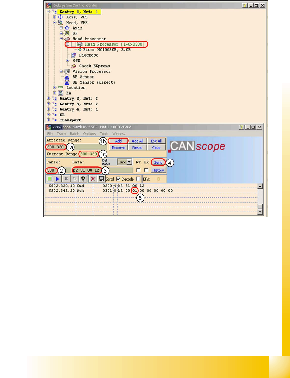
4.4 - 13: Read the board type ID Head interface
X (1) Restrict the address range for the CAN ID. Specify the smallest possible range at
Affected Range
, to reduce the counter of CAN Bus commands which appears in the network
window.
X Confirm with
Add
X The CAN ID range will now be shown at
Current Range
.
X (2) At
CanID
enter the relevant ID.
X (3) At
Data
enter the CAN command.
E.g.
B2 31 00 12
b2
--> read EEPROM
31
--> read out from head interface
12
--> Storage location in EEPROM memory in hex
X (4) Press
Send
.
X (5) Command will be shown in the network window and an answer will be sent (acknowledgment).
Ack
B2 00 01 00 00 00 00 00
--> Storage location 12 is occupied with the value
01
= board ID
head interface.
Communication and Control
Board type recognition Troubleshooting, if are missing two board type ID‘s
Student Guide SIPLACE D4 (FSE)
Communication and Control EN 09/2006
104
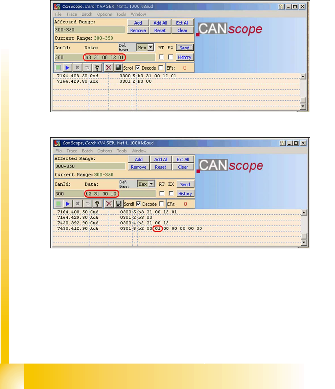
X Write the correct board ID with the command
B3 31 00 12 01
B3
--> write to EEPROM
31
--> head interface
12
--> storage location in EEPROM
01
board ID for head interface
Reply
B3 00
--> command OK
4.4 - 14: Writing the CAN command board ID on the head interface
X Check the board type ID after you written the ID in the EEPROM
4.4 - 15: Check the written board type ID
X Download the applications software on the TQM module.
> After performing the download, the TQM module should load again without error messages.
4.4.3 Troubleshooting, if are missing two board type ID‘s
If two IDs are missing, preventing the machine (TQM module) from booting, use the default CAN ID to
address the TQM module at the head processor (CAN ID +4hex) (see Section 4.4.2.2 Reading and Wri-
ting the Board IDs with CAN Commands [J 96]).