00195193-02 SG D4 FSE en (1).pdf - 第118页
Reference run Completion of the Z-axis reference run Reference Run C&P12 Student Guide SIPLACE D4 (FSE) EN 09/2006 Reference run 111 5.3.6 Completion of the Z-a xis reference run 5.3.7 Reference Run at Dp-axis The fu…
Reference run
Reference Run C&P12 Preparation for z-axis reference run
Student Guide SIPLACE D4 (FSE)
Reference run EN 09/2006
110
5.3.4 Preparation for z-axis reference run
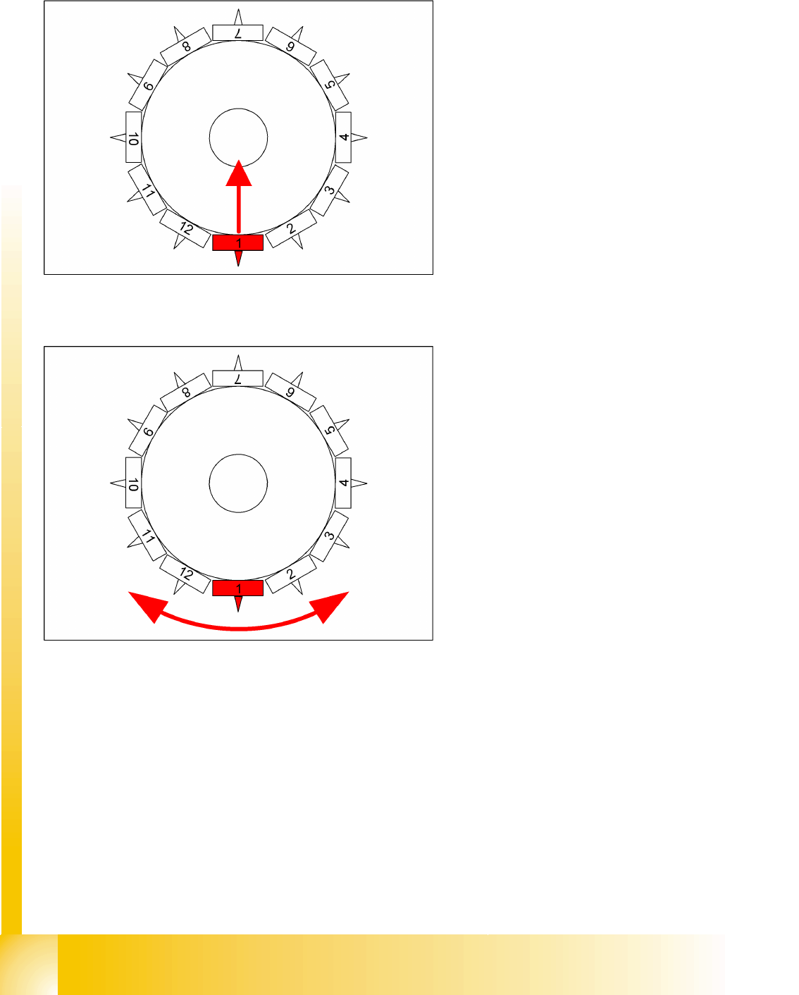
5.3.5 Reference run at star-axis
The Z-axis runs to uppermost end stop. When
stand still is detected the Z-axis runs down by 30
digits with reduced force. This Z-axis position with
reduced force enables the placement star to move
into reference position.
The star-axis turns counter clockwise to zero point
pulse of the incremental shaft encoder. The zero
point correction is loaded. The star-axis turns
clockwise (according the zero point correction)
until the position counter shows 0 digit.
Segment 1 is now in the pickup/placement
position.
Reference run
Completion of the Z-axis reference run Reference Run C&P12
Student Guide SIPLACE D4 (FSE)
EN 09/2006 Reference run
111
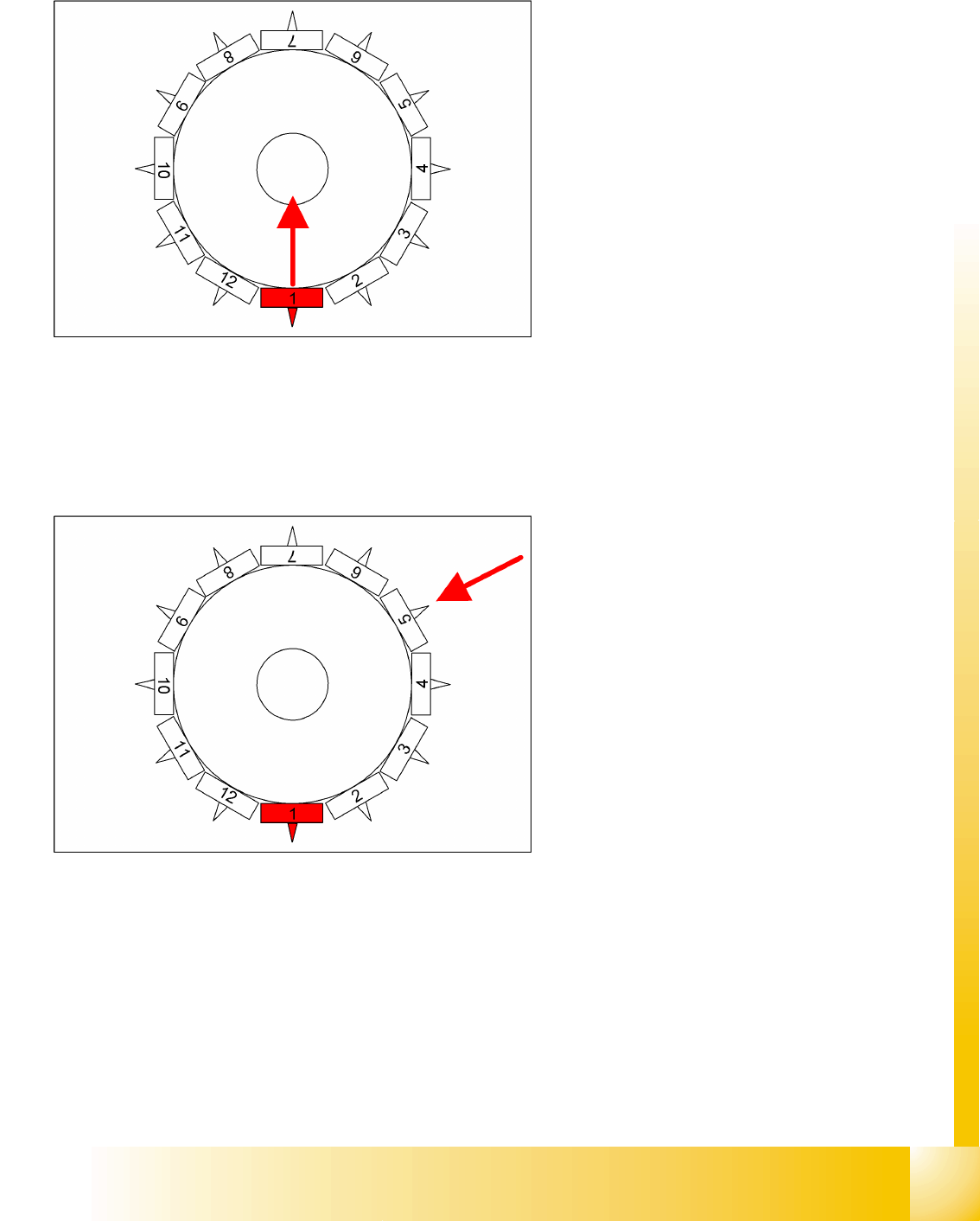
5.3.6 Completion of the Z-axis reference run
5.3.7 Reference Run at Dp-axis
The function of the DP axis is, to turn the nozzle in the correct pick up angle. After the component
recognition the DP-axis turn the components in correct placement angle.
C&P reference run completed!
This is followed by the gantry reference run (see section Gantry).
The star axis rotates to 6250/6750 digits. At
these positions, there is a segment ball
bearing between the Z-axis claw and the
circular arc. guide. The various different star
positions compensate a Z-0 correction angle
error.
The Z-axis moves to the bottom end position
stop for the 1st star position and to thetop end
position stop for the 2nd star position.
The average value of these results is
calculated and sent to the axis control system
as a negative reference value (ZPC).
Star-axis is moved back to reference position.
The Z-axis restarts the reference run with the
new zero point correction value.
The segment now in the DP-station is turned to
reference position. (segment 5 for 12 nozzle
head.)
Sequence: the DP-station swivels in. The axis
starts and searches for the zero pulse. The
DP-station swivels out after the end signal.
The swiveling function is controlled by the
CAN-Bus.
The rotation of the sleeve is regulated by the
axis controller, which contains the DP position
encoder.
The zero point correction on the DP-axis is
always 0 (because up to 12 segments are
operated by one drive).
Reference run
Reference Run C&P12 Sequence vacuumcheck
Student Guide SIPLACE D4 (FSE)
Reference run EN 09/2006
112
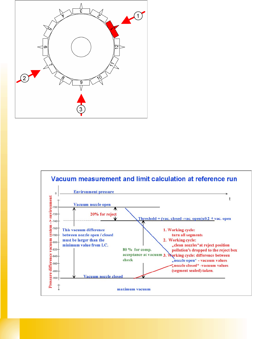
5.3.8 Sequence vacuumcheck
5.3.9 Determining the Vacuum and Threshold Values
5.3 - 2: Measuring and calculating the vacuum values for a reference run
Contaminants and components are released or
removed and nozzles are rotated to 0°.
The gantry axes move the Collect & Place
head to the reject position.
The star axis moves counterclockwise and all
three functions are performed within one head
cycle.
1. The DP-station is swiveled in and turns each
segment to 0° position.
2. The air kiss valve is opened, the valve drive of
the reject position is activated and switches
between open and closed. Anything on the
nozzle is rejected. The air kiss valve is closed.
The gantry axes move the Collect & Place
head to the fixed conveyor side.
3. where the vacuum reference values are
measured at the pickup/placement station.
These are the reference values for each
segment for the vacuum checks during
placement.