00195193-02 SG D4 FSE en (1).pdf - 第119页
Reference run Reference Run C&P12 Sequence vacuumcheck S tudent Guide SIPLACE D4 (FSE) Reference run EN 09/2006 11 2 5.3.8 Sequence vacuumcheck 5.3.9 Determining the V ac uum and Threshold V alues 5.3 - 2: Measuring …
Reference run
Completion of the Z-axis reference run Reference Run C&P12
Student Guide SIPLACE D4 (FSE)
EN 09/2006 Reference run
111
5.3.6 Completion of the Z-axis reference run
5.3.7 Reference Run at Dp-axis
The function of the DP axis is, to turn the nozzle in the correct pick up angle. After the component
recognition the DP-axis turn the components in correct placement angle.
C&P reference run completed!
This is followed by the gantry reference run (see section Gantry).
The star axis rotates to 6250/6750 digits. At
these positions, there is a segment ball
bearing between the Z-axis claw and the
circular arc. guide. The various different star
positions compensate a Z-0 correction angle
error.
The Z-axis moves to the bottom end position
stop for the 1st star position and to thetop end
position stop for the 2nd star position.
The average value of these results is
calculated and sent to the axis control system
as a negative reference value (ZPC).
Star-axis is moved back to reference position.
The Z-axis restarts the reference run with the
new zero point correction value.
The segment now in the DP-station is turned to
reference position. (segment 5 for 12 nozzle
head.)
Sequence: the DP-station swivels in. The axis
starts and searches for the zero pulse. The
DP-station swivels out after the end signal.
The swiveling function is controlled by the
CAN-Bus.
The rotation of the sleeve is regulated by the
axis controller, which contains the DP position
encoder.
The zero point correction on the DP-axis is
always 0 (because up to 12 segments are
operated by one drive).
Reference run
Reference Run C&P12 Sequence vacuumcheck
Student Guide SIPLACE D4 (FSE)
Reference run EN 09/2006
112
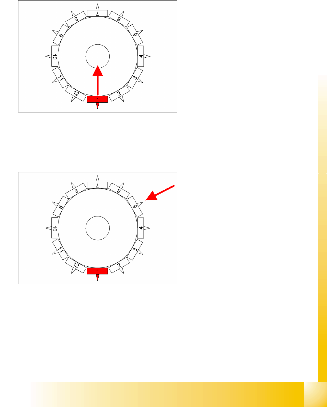
5.3.8 Sequence vacuumcheck
5.3.9 Determining the Vacuum and Threshold Values
5.3 - 2: Measuring and calculating the vacuum values for a reference run
Contaminants and components are released or
removed and nozzles are rotated to 0°.
The gantry axes move the Collect & Place
head to the reject position.
The star axis moves counterclockwise and all
three functions are performed within one head
cycle.
1. The DP-station is swiveled in and turns each
segment to 0° position.
2. The air kiss valve is opened, the valve drive of
the reject position is activated and switches
between open and closed. Anything on the
nozzle is rejected. The air kiss valve is closed.
The gantry axes move the Collect & Place
head to the fixed conveyor side.
3. where the vacuum reference values are
measured at the pickup/placement station.
These are the reference values for each
segment for the vacuum checks during
placement.
Reference run
Measuring Nozzle Lengths for Component Recognition by the Component Sensor Reference Run C&P12
Student Guide SIPLACE D4 (FSE)
EN 09/2006 Reference run
113
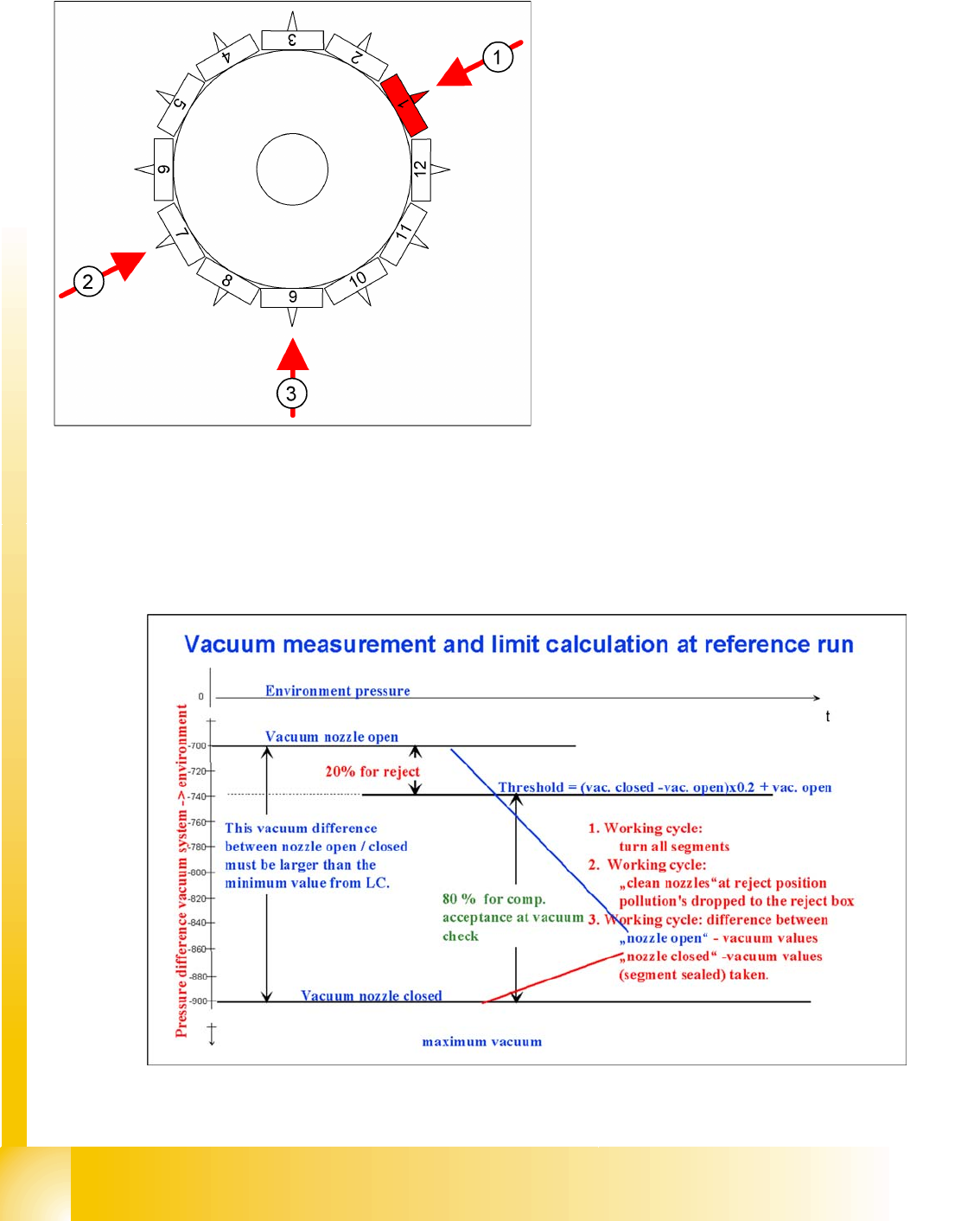
Legend
1. The vacuum is measured twice at the reference point: once with closed and once with open valve,
while air flows through the nozzle.
2. The value with closed valve depends on the ambient pressure and may vary significantly, according
to the local weather conditions and altitude. The higher the ambient pressure, the lower the vacuum
at closed valve.
3. The value by open valve depends on the nozzle size and condition. The smaller the nozzle, the
greater the open valve value will be. A contaminated or blocked nozzle will also give a higher valve.
4. The difference between the open and closed nozzles has been preset by the line computer as an
ideal case minimum value. This value is different for all nozzle types e.g. 120 mbar for 714, 704, 914
and 904 nozzles. If these values are not achieved, the error message "Vakuumdifferenz offen-
geschlossen zu gering" (vacuum difference open-closed is too low) will appear.
5. The threshold for component acceptance is also set now. In this case we have a value of 700 mbar
when the nozzle is open and a value of 900 mbar when the nozzle is closed. The calculation is
performed as follows:
Threshold = (900(closed) - 700(open))= x 0.2 + 700(open) = 200 x 0.2 + 700 = 740
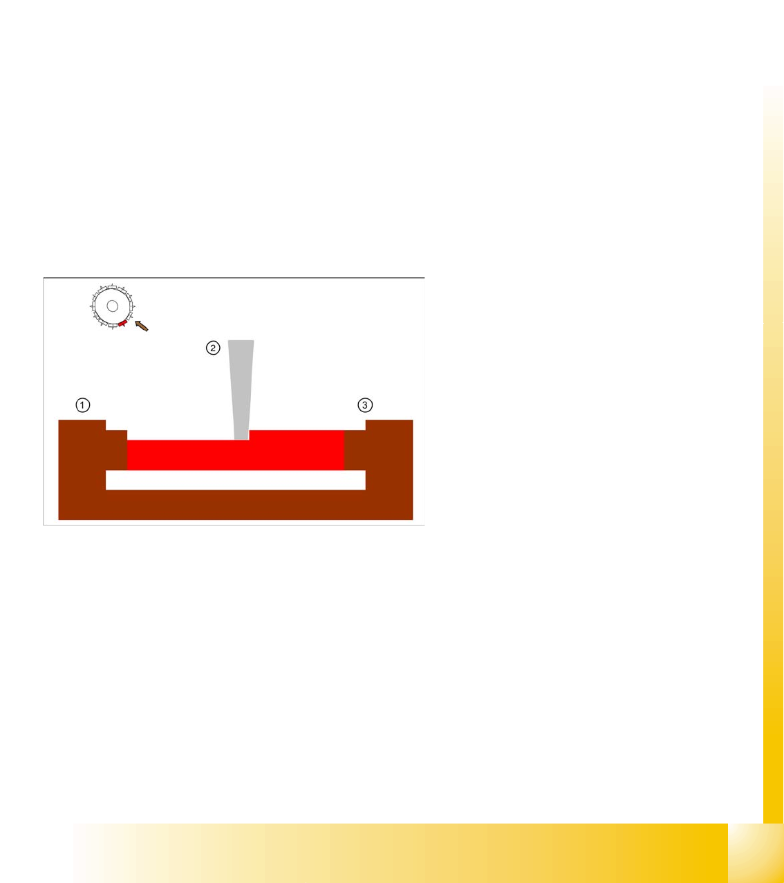
5.3.10 Measuring Nozzle Lengths for Component Recognition by the Component
Sensor
The component sensor option can only be used with machine stations SW 503 or higher and only with
12 nozzle C&P placement heads.
If the CO sensor option is installed on the C&P12, the following will be performed during the vacuum
reference run:
The length of the nozzle in the IR beam will be measured during star revolution.
The SIPLACE Pro/LC defines which nozzle type can be measured (nozzle lengths longer than
12 mm). Nozzle setup on the placement star triggers measurement.
Before pickup, the length of the empty nozzle is compared to the value measured during the
reference run.
During the placement process, component recognition refers to the empty nozzle measurement
value before placement is performed.
Legend:
1. IR receiver
2. Nozzle
3. IR transmitter