00195193-02 SG D4 FSE en (1).pdf - 第137页
Services to the machine Power Supply Unit Safety and Signaling Circuit S tudent Guide SIPLACE D4 (FSE) Services to t he machine EN 09/2006 130 6.2.14.2.5 Feeder Cover Flap Control Circuit 6.2 - 10: Feeder cover flap cont…
Services to the machine
Safety and Signaling Circuit Power Supply Unit
Student Guide SIPLACE D4 (FSE)
EN 09/2006 Services to the machine
129
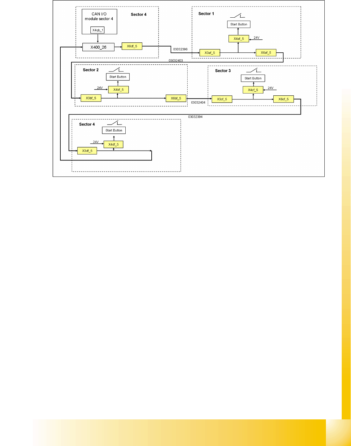
6.2.14.2.4 Start Button Circuit
6.2 - 9: Start button circuit
The start button circuit consists of 4 contacts and they are switched in parallel mode. If one or more
START buttons has been pressed, the contact will close and the 24 V will be present at the input of the
CAN I/O module in sector 4, showing that one of the START buttons has been pressed.
Services to the machine
Power Supply Unit Safety and Signaling Circuit
Student Guide SIPLACE D4 (FSE)
Services to the machine EN 09/2006
130
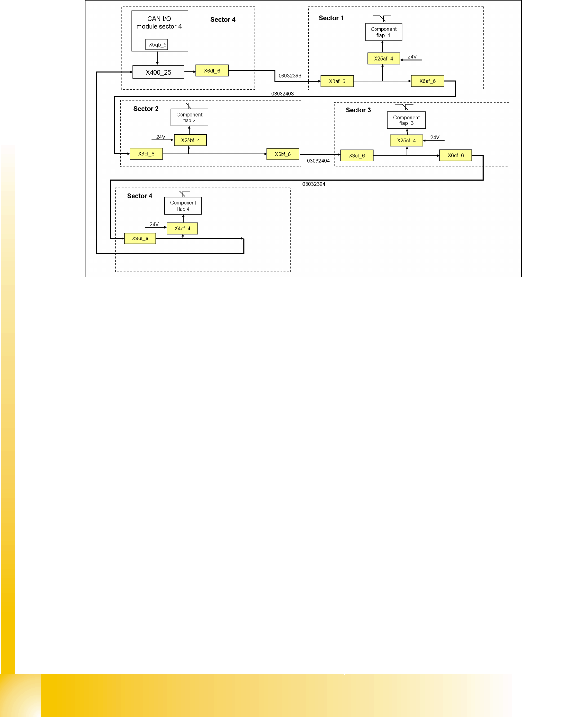
6.2.14.2.5 Feeder Cover Flap Control Circuit
6.2 - 10: Feeder cover flap control circuit
The feeder cover flap circuit consists of 4 contacts, which are switched in parallel mode. If one or more
feeder cover flaps are open, the contact will close and 24 V will be present at the input of the CAN I/O
module in sector 4. This indicates that one of the feeder cover flaps has been opened.
Services to the machine
Safety and Signaling Circuit Power Supply Unit
Student Guide SIPLACE D4 (FSE)
EN 09/2006 Services to the machine
131
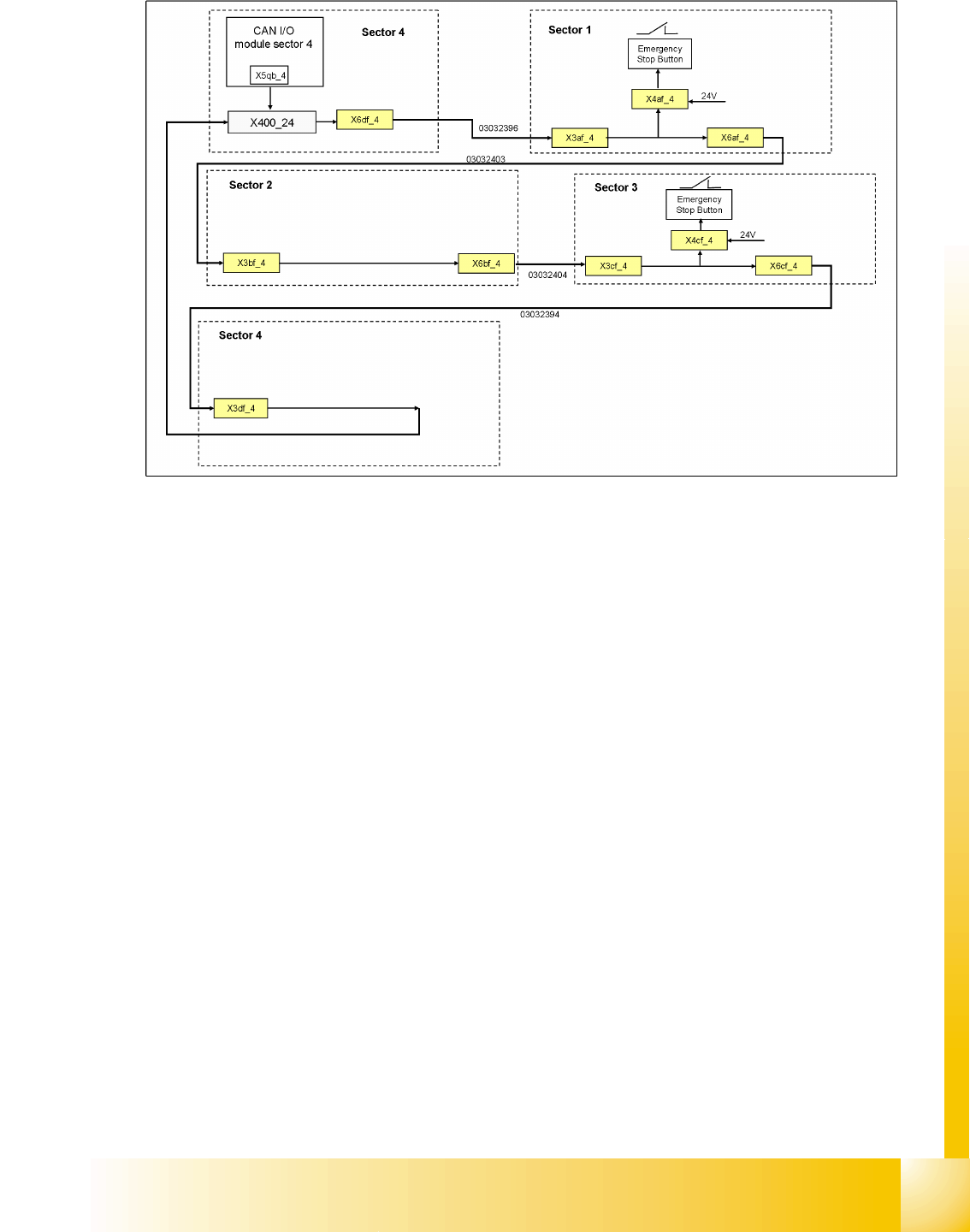
6.2.14.2.6 Emergency Stop Button Control Circuit
6.2 - 11: Emergency stop button control circuit
The emergency stop button circuit consists of 2 contacts, which are switched in parallel mode. If one or
more emergency stop buttons are closed (pressed), the contact will close and 24 V will be present at the
input of the CAN I/O module in sector 4. This will be shown on the station software interface.
If both emergency stop buttons are open (not pressed), 0 V will be present at the input of the CAN I/O
module.