00195193-02 SG D4 FSE en (1).pdf - 第141页
Services to the machine Power Supply Unit Protective Combination Device (Relay K1) S tudent Guide SIPLACE D4 (FSE) Services to t he machine EN 09/2006 134 6.2.15.1 Via PCC K1 The protective contactor combin ation (PCC) K…
Services to the machine
Protective Combination Device (Relay K1) Power Supply Unit
Student Guide SIPLACE D4 (FSE)
EN 09/2006 Services to the machine
133
6.2.15 Protective Combination Device (Relay K1)
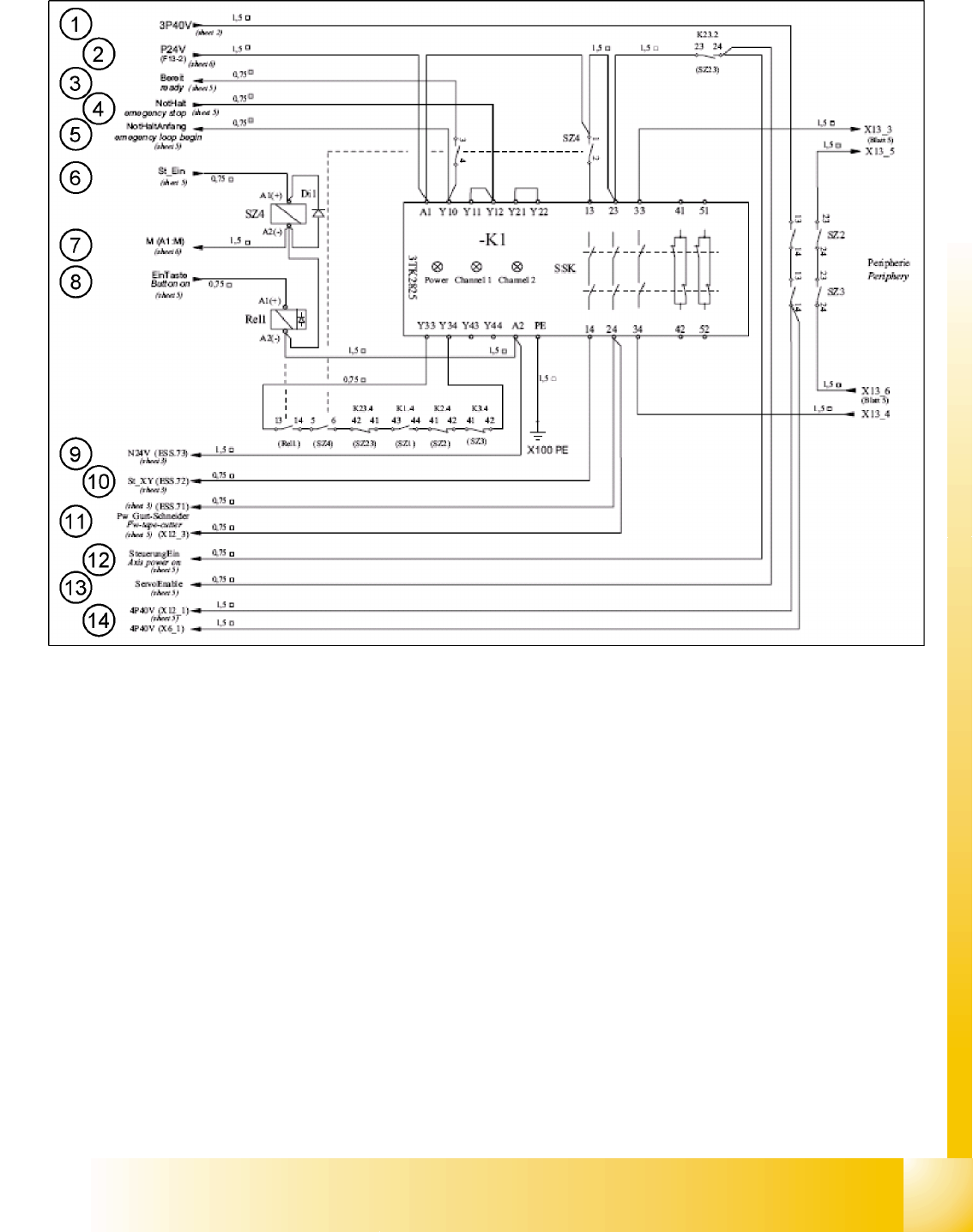
Legend
1. Input: 40 V DC switched from SZ2 and SZ3 for the conveyor and the component counter under the
traverse (not used)
2. Input: 24 V DC from F13 for A1 + relay K1
3. Output: Ready signal to input of CAN I/O module (signal K1 is OK)
4. Input: Emergency stop signal, safety loop OK
5. Output: Start safety loop
6. Input: (feedback) control ON – signal from axis units 1 and 2 (24 V SZ4 A1+)
7. GND signal from 24 V power pack
8. Input: Start button signal 24 V relay 1 A1(+)
9. Output: GND 24 V – signal for the inrush current limiter
10. Output: St_XY – (control_XY) - release signal 200 VDC for X and Y servo
11. Output: Tape cutter voltage – release signal 24 VDC for the tape cutter
12. Output: Axis voltage ON SZ23
13. Output: Servo release SZ23
14. Output: 40 V DC switched from SZ2 and SZ3 for the conveyor and the component counter under the
traverse (not used)

Services to the machine
Power Supply Unit Protective Combination Device (Relay K1)
Student Guide SIPLACE D4 (FSE)
Services to the machine EN 09/2006
134
6.2.15.1 Via PCC K1
The protective contactor combination (PCC) K1 is used as a standard combined protective device. Its
complex configuration, consisting of 3 relays, guarantees maximum protection and operation safety.
The contactor status is shown by LEDs (Power, Channel 1 and Channel 2).
The PCC can be operated via 1 or 2 channels (safety loops).
The D4 only uses one channel, while the other channel is bridged (terminal clamps Y21 and Y22). This
means that the LEDs for both channels shine when the PCC is switched on.
The protective contactor combination K1 switches the contacts 13 and 14, 23 and 24, 33 and 34, plus
the relays SZ2, SZ3 and SZ23.
When this has been completed, K1 is understood to be in the status
24 V supply ON
and the 3 LEDs
Power, Channel 1 and Channel 2 will shine.
6.2.15.2 How is the PCC K1 Enabled?
Precondition:
X The machine must be switched on. Voltage is then present at main contactor SZ1, which is supplied
with 34 V by the transformer and rectifier V7. After SZ1 has contacted, full voltage is present at
transformer T1.
The 24 V voltage supply is now active via fuse F13 and supplies PCC A1 with 24 V. Contactors 13
and 23 of the PCC are switched with relay SZ4.
X The safety loop must be closed, so that 24 V is present at contacts Y10, 11 and 12. That means, the
protective covers, the emergency stop button, the component tables and the feeder cover flaps all
need to be connected/closed.
X The ready signal informs the software that the PCC has triggered and that everything is OK.
6.2.15.3 Pressing the Start Button
Pressing the start button triggers the following actions:
The start signal pulse enables relay 1 and closes contacts 13 and 14.
The 24 V software release signal is sent via the I/O assembly output to relay SZ4, which then closes
contacts 5 and 6.
Contacts 13 and 14, 23 and 24, 33 and 34 of the PCC are now closed.
The
St_XY
signal is sent via contact 14 of the PCC to the inrush current limiter input. Relay 1 is
enabled via NTC thermistors. The relay 1 contacts simultaneously switch the ground A2 (-) of relays
SZ2 and SZ3. Voltage U/V/W_XY is now transmitted via the inrush current resistors until relay 2 of
the inrush current limiter is enabled.
Relay 2 switches SZ23 and full voltage is then present at the X and Y servos.
The voltage flows directly via the relays.
Services to the machine
Various Signals Power Supply Unit
Student Guide SIPLACE D4 (FSE)
EN 09/2006 Services to the machine
135
6.2.16 Various Signals
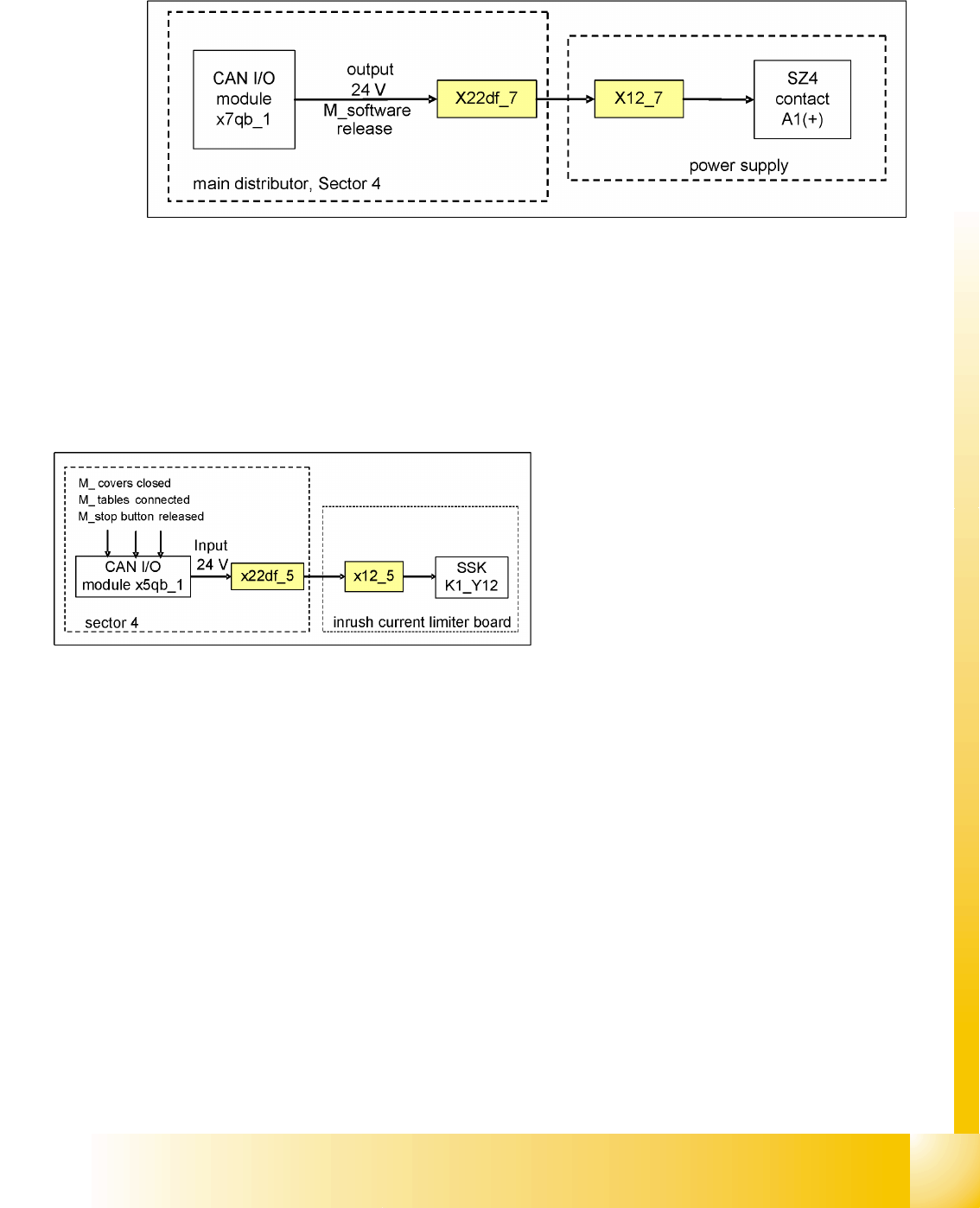
6.2.16.1 Software Release (Software Enabled)
6.2 - 12: Software release signal
The software release signal is emitted by the CAN I/O card, as soon as the MC has finished booting and
the start button has been pressed. Communication also needs to be established to the Vision system,
the axis controllers, the CAN bus and the stations/line computers (except in stand-alone mode). Once
the start button is pressed, the 24 V output signal is sent via the CAN I/O module to SZ24, contact A1.
If the emergency stop circuit is broken, the software release will not be given.
6.2.16.2 Safety Loop OK signal
The message
Safety loop OK
will be emitted by
the CAN I/O module, if the following conditions
have been fulfilled:
All covers closed
All component tables connected
All emergency stop buttons released
The emergency stop circuit is closed