00195193-02 SG D4 FSE en (1).pdf - 第152页
Axis dynamic Track signals and Zero pulse signal Position measuring system Student Guide SIPLACE D4 (FSE) EN 09/2006 Axis dynamic 139 7 Axis dynamic 7.1 Position measuring system 7.1.1 T rack signals a nd Zero pulse sign…

Services to the machine
Pneumatic System Bulk Case System and Nozzle Changer
Student Guide SIPLACE D4 (FSE)
Services to the machine EN 09/2006
144
Axis dynamic
Track signals and Zero pulse signal Position measuring system
Student Guide SIPLACE D4 (FSE)
EN 09/2006 Axis dynamic
139
7 Axis dynamic
7.1 Position measuring system
7.1.1 Track signals and Zero pulse signal
Our Axes systems consists of the following parts.
Axis controller for main board
Servo amplifier
Motor
Position measuring system with incremental scale and encoder
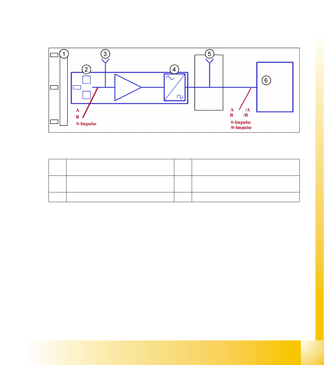
7.1 - 1: Principle circuit for position measuring systems
Legend
The axis control system with closed position control circuit determines the axis position directly,
based on the mechanical movement of the axis. The position measurement system generates analog
track and zero pulse signals during movement over the incremental scale. An amplifier, a multiplier
switch and a signal former are integrated into the amplifier housing. A test connector for digital signals
is either installed on the next interface board or the digital signals are measured at track A/B and the zero
pulse output of the SIPLACE axis tester. The track signals are the only feedback loops in all the axis
control systems of the SIPLACE machine. This means that each track recognition error affects the axis
control system. The gantry axes immediately stop at a fault; the head axes finish the positioning to target
before showing a track signal error.
1 Incremental scale with zero pulses 4 Electronic signal multiplication and signal
digitalization
2 Incremental encoder for track A/B and zero
pulse signals (O pulse.)
5 Test output digital signals
3 Analoge signal output and amplifier 6 Axis controller
Axis dynamic
Position measuring system Track signals and Zero pulse signal
Student Guide SIPLACE D4 (FSE)
Axis dynamic EN 09/2006
140
The position is determined by a position counter on the axis controller. The moving direction of the axis
is determined by the phase shift of the track signals An advanced track A signal indicates movement to
the right, while an advanced track B signal indicates movement to the left. To make the encoder system
robust for the high resolution we multiply the frequency of the analoge signal and create a high resolution
digital measuring system.
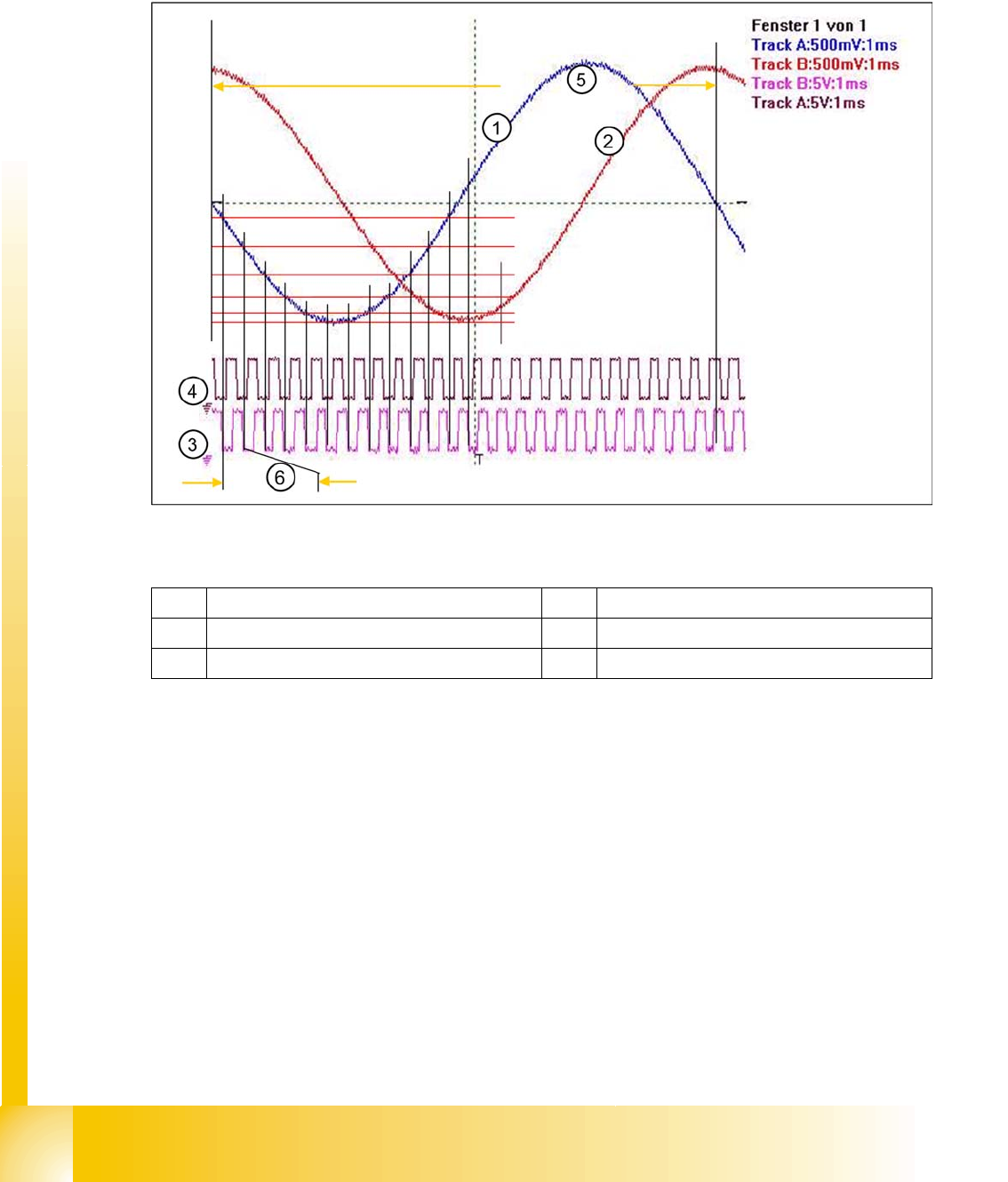
7.1 - 2: Principle signal multiplication at analog Track signals of a gantry axis
Legend
The signal multiplication can be realized as a Schmitt trigger action. During comparison of the analog
and digital axis signals, a signal multiplication of 25 (see diagram above), 10 or just 1 can be recognized.
The track signals of the C&P head axes can only be measured as digital signals i.e. The analog signals
are directly converted in the transmitter housing, without provision of a test connection for the analog
signals.
1 Analog track A signal incremental encoder 4 Digital track B signal at Test connector
2 Analog track B signal Incremental encoder 5 Period time of analog track signal
3 Digital track A signal at Test connector 6 Period time of digital track signal