00195193-02 SG D4 FSE en (1).pdf - 第162页
Axis dynamic Servo amplifier TBS .. and SDS ... Axis dynamic basics Student Guide SIPLACE D4 (FSE) EN 09/2006 Axis dynamic 149 So there is nothing to adjust all this axes have a dyn amic behav ior. Each axis has friction…
Axis dynamic
Axis dynamic basics Servo amplifier TBS .. and SDS ...
Student Guide SIPLACE D4 (FSE)
Axis dynamic EN 09/2006
148
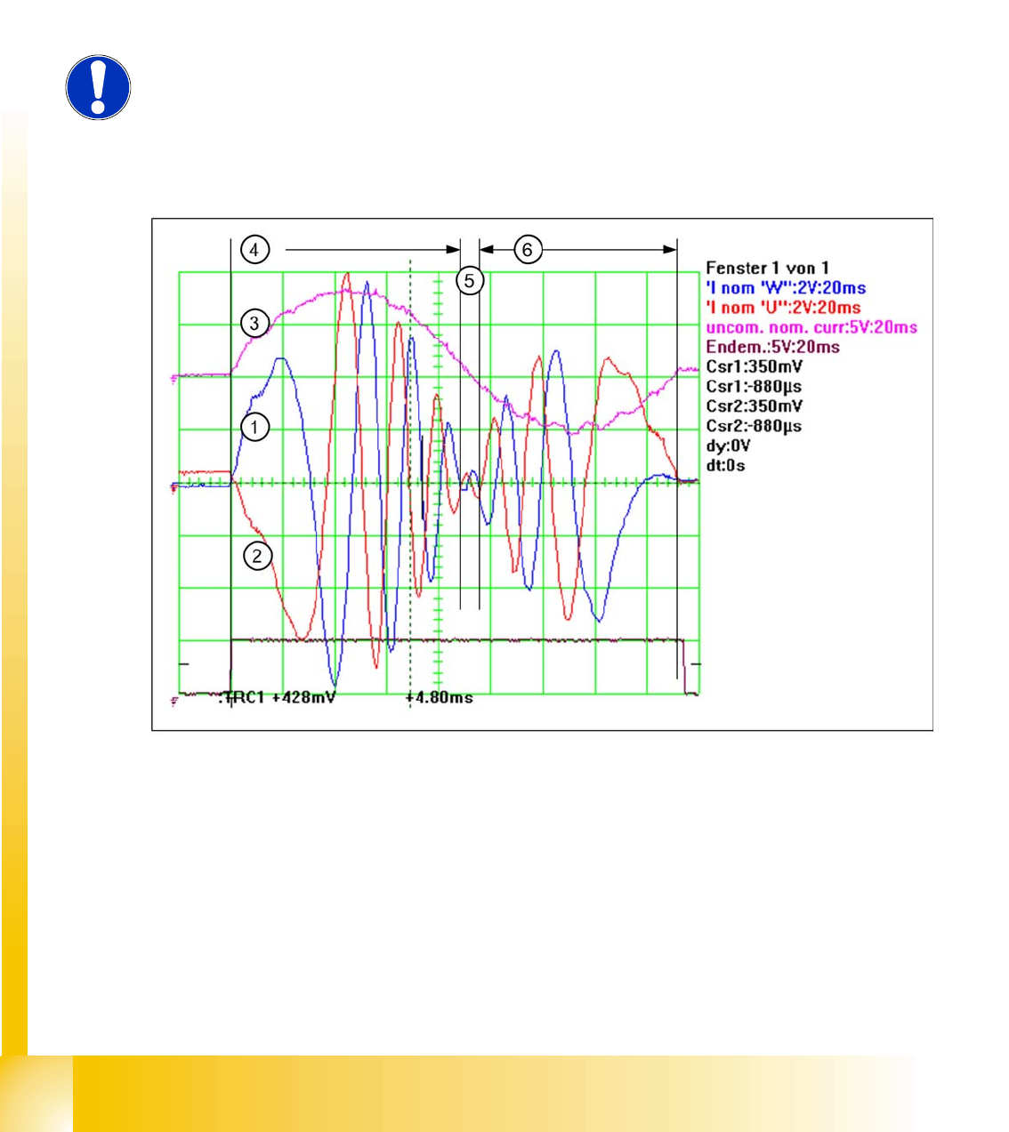
For assessment of the axis dynamics by a service technician, the system generates an uncommutated
current target signal from all motor current target signals. This informs you about the mechanical friction
in the axis system. This can be measured on the adapter board of the axis test box or at the Vreg output
of the SIPLACE axis tester (SAT).
The uncommutated target current signal is an envelope signal for the 2 visible motor current target
signals from the axis controller. The missing 3rd motor current signal is calculated at the Servoboard.
The known V nominal (V-target) speed signal and the force signal have been replaced by the motor
current target signals for DC or AC drives.
7.3 - 5: The uncommutaded nominal current signal (3) and the motor current signals (1) (2) of a AC Motor
The acceleration section can be recognized in the motor current target signal of the AC motor (4), due
to the high amplitudes needed to supply the axis mechanics with sufficient force. The frequency of this
signal section is low, due to the low speed. The amplitude becomes lower and lower because the
necessary motor force is reduced with increasing speed.
The frequency becomes higher because the speed of the motor is increased to a maximum for the
constant speed section (2).
In the deceleration section, the amplitude increases again, to reduce the speed of the axis mechanics.
The frequency become lower and lower (3). Finally, the axis is moved into the correct target position,
with overshoot control.
NOTE:
These motor current signals can be measured at the V nominal and the Force
output of the axis tester. The same signals are measured at the two topmost test
points of the servo amplifier board, as Inom. U’ and Inom. W signals.
Axis dynamic
Servo amplifier TBS .. and SDS ... Axis dynamic basics
Student Guide SIPLACE D4 (FSE)
EN 09/2006 Axis dynamic
149
So there is nothing to adjust all this axes have a dynamic behavior. Each axis has friction to be
overcome. The higher the friction is, the higher the amplitudes will be at acceleration and constant
speed. The higher motor force at acceleration and constant speed can be detected at the uncommutated
motor current target signal. Higher friction reduces the required motor force during the deceleration
section, so that the amplitude is smaller for the uncommutated motor current target signal.
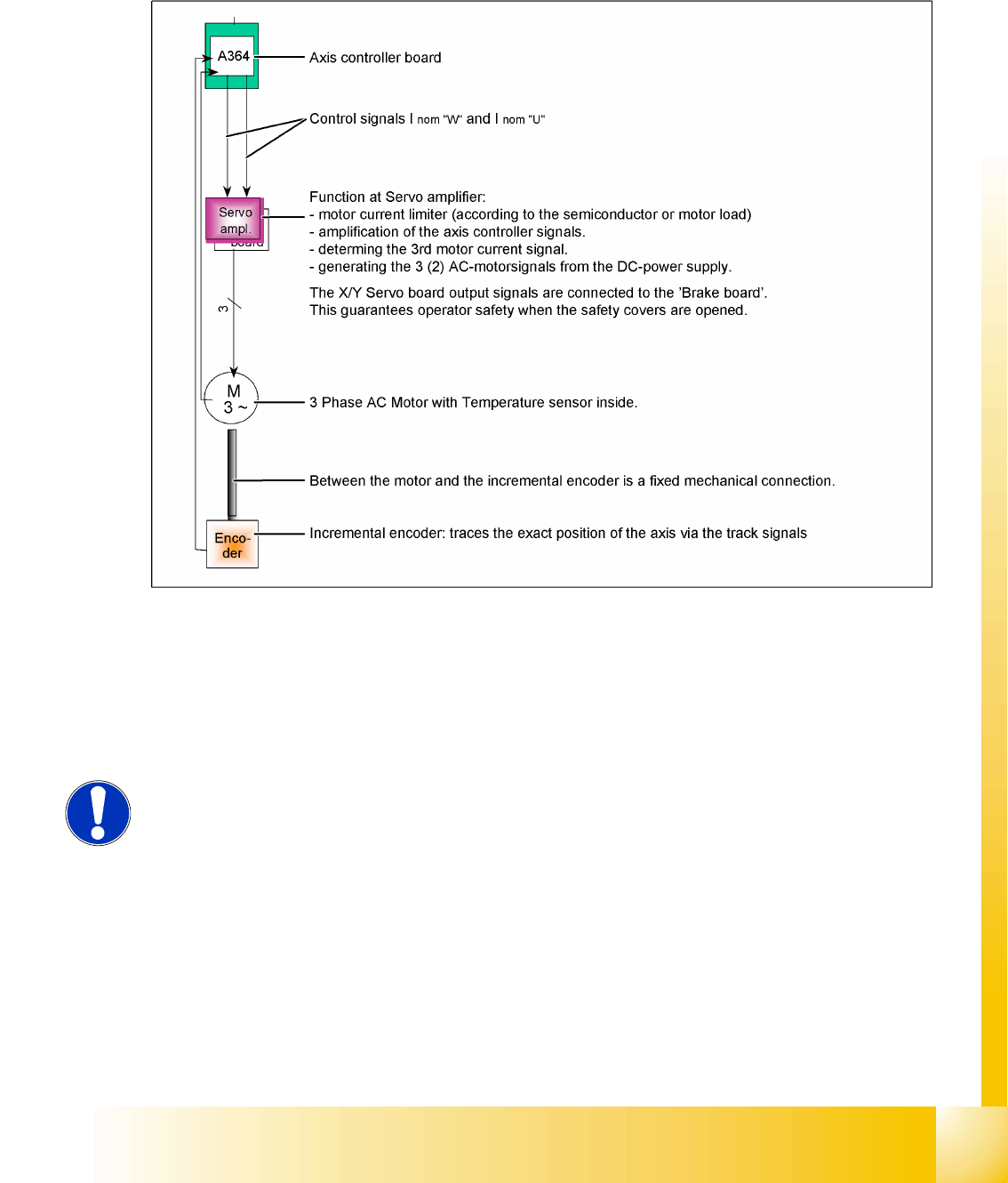
7.3 - 6: Axis block diagram example X or Y-axis of HF/Siplace X machine
Although the various axis types differ in details, all control tasks are handled by the axis controller. Two
control signals for 2 or 3 phase axis drive are transmitted to the servo. For DC drives, we use the same
hardware principle, with only one control signal to the servo amplifier. The only feedback is provided by
the track signals from the incremental encoder to the axis controller - a tacho (Z/DP axis) is not
connected to the axis system.
See also:
J 7.3 Axis dynamic basics [J 144]
NOTE:
Mechanical and electrical faults can be detected by analyzing the axis controller
signal paths.
Axis dynamic
Axis control gantry Track signals and Zero pulse
Student Guide SIPLACE D4 (FSE)
Axis dynamic EN 09/2006
150
7.4 Axis control gantry
7.4.1 Track signals and Zero pulse
7.4.1.1 Check the zero pulse signal
The zero pulse on the incremental scale must be recognized from the incremental encoder secure and
perfectly. To check the zero pulse you can check the analog or digital zero pulse. If the zero pulse is not
recognized correctly, the axis will reference to a spurious peak. Placement offsets will be the result.
Electrical settings can not be made in the incremental length measurement system.
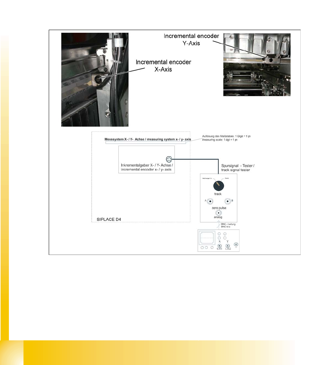
7.4.1.1.1 Measurement of the analog zero pulse signal
7.4 - 1: Measurement procedure for checking the analog zero pulse and the analog track signals
Test procedure
X Connect the measurement tester to the incremental encoder.
X Main switch
ON
X Connect the oscilloscope to the measurement tester.
X Set up the measurement adapter
Calibrate the oscilloscope
and position the signal at the top,
center of the screen.