00195193-02 SG D4 FSE en (1).pdf - 第165页
Axis dynamic Axis control gantry Track signals and Zero pulse S tudent Guide SIPLACE D4 (FSE) Axis dynamic EN 09/2006 152 7.4.1.1.2 Measuring the Digit al Zero Pulse Signal 7.4 - 2: Measurement procedure for checking the…
Axis dynamic
Track signals and Zero pulse Axis control gantry
Student Guide SIPLACE D4 (FSE)
EN 09/2006 Axis dynamic
151
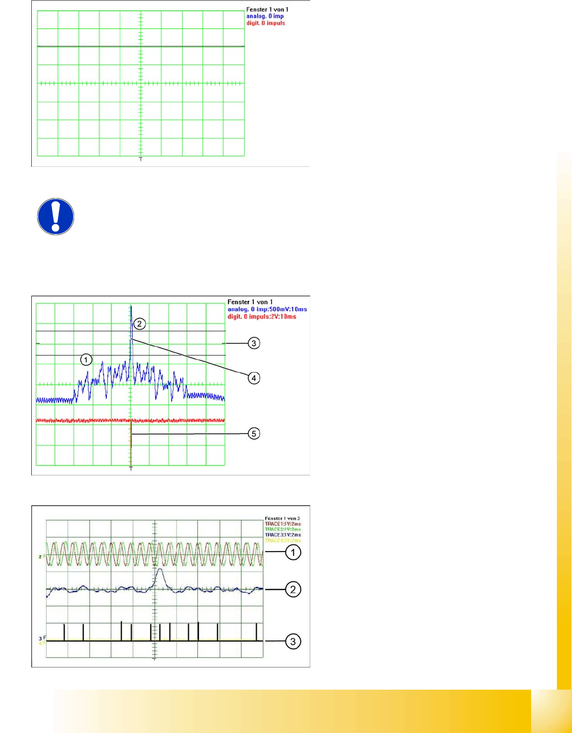
X Move by hand the gantry over the first zero pulse.
X The following picture should appear.
NOTE:
The first zero pulse is to be checked at a distance of 25 mm after the bumper.
Legend:
1. In the tolerance space of - 0.3 V there is no
interference pulse.
2. The analog zero pulse has to over the
tolerance space more then 0,3V
3. Initial start position
4. analog zero pulse
5. digital zero pulse
Legend:
1. analog track signal A and B
2. analog zero pulse
3. digital zero pulses
Axis dynamic
Axis control gantry Track signals and Zero pulse
Student Guide SIPLACE D4 (FSE)
Axis dynamic EN 09/2006
152
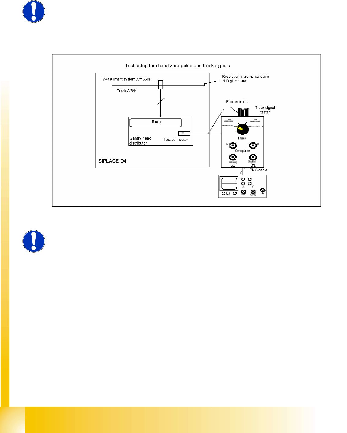
7.4.1.1.2 Measuring the Digital Zero Pulse Signal
7.4 - 2: Measurement procedure for checking the digital zero pulse signal and the digital track signals.
NOTE:
You can also use the BNC socket on the axis test box to check the zero pulse
signal (inverted display of zero pulse signal). The digital signals can be checked
at connectors X11 and X24 of the gantry distributor and gantry head distributor
(for error monitoring purposes). (Y-Axis, calculate extra time for dismounting
the covers)
NOTE:
The digital track signals can be checked with measurement clamps attached to
the test connector!
Axis dynamic
Track signals and Zero pulse Axis control gantry
Student Guide SIPLACE D4 (FSE)
EN 09/2006 Axis dynamic
153
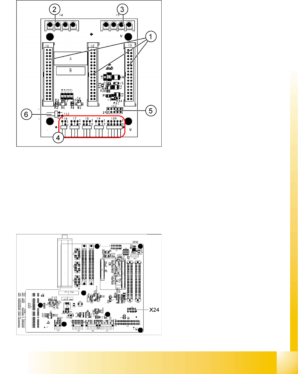
X11 on Y-axis gantry interface
X24 on X-Axis Gantry Head Distributor
Legend:
1. X1/X2/X3 flat ribbon cable
2. X4 motor Y-axis (U,V,W)
3. X5 motor X-axis (U,V,W)
4. X6 X-motor temperature sensor
X7 end position proximity switch for Y-axis (not
in use)
X8 reference proximity switch for Y-axis (not in
use)
X9 anti-crash sensor (not in use)
X10 connector for Y-axis track signals
5. X11 test connector for Y-axis track signals
6. X12 temperature sensor for Y-axis motor
Connector assignment X11
Pin 1 Ground
Pin 2 Track A
Pin 3 Track A\ A\ mean inverted A
Pin 4 Ground
Pin 5 Track B
Pin 6 Track B\
Pin 7 +5V
Pin 8 Track N
Pin 9 Track N\
Pin 10 Key
Connector assignment X24
Pin 1 Ground
Pin 2 Track A
Pin 3 Track A\
Pin 4 Ground
Pin 5 Track B
Pin 6 Track B\
Pin 7 +5V
Pin 8 Track N
Pin 9 Track N\
Pin 10 Key