00195193-02 SG D4 FSE en (1).pdf - 第172页
Axis dynamic Check dynamic Y- axis Axis control gantry Student Guide SIPLACE D4 (FSE) EN 09/2006 Axis dynamic 159 7.4.3 Check dynamic Y - axis 7.4.3.1 T est set up 7.4.3.2 Y -axis T ravel Profiles for C&P12 7.4.3.3 Y…
Axis dynamic
Axis control gantry Check dynamic X-axis
Student Guide SIPLACE D4 (FSE)
Axis dynamic EN 09/2006
158
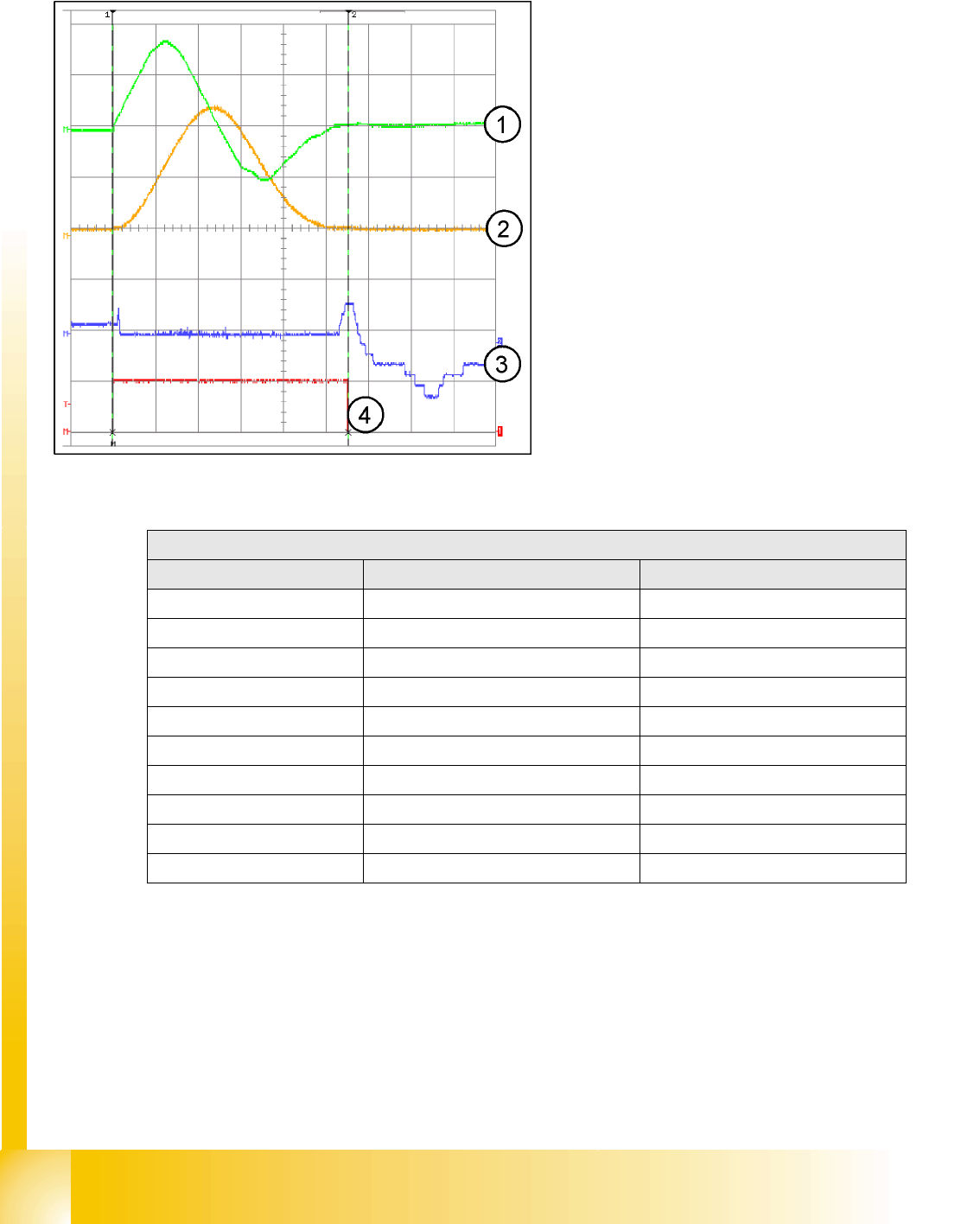
7.4.2.3 X-axis Travel Profiles for C&P12
7.4.2.4 X-axis Travel Time Table
Legend:
1. Current signal
2. Speed – signal Vreg (Vnominal)
3. Deviation of position
4. End signal
Distance: 15mm = 15000 Digit
Time: 56 +/-5ms
X-axis gantry axis with DLM2 (C&P12)
Distance / Digit Time / ms Tolerance /ms
500 32 +/-5
1000 34 +/-5
2000 38 +/-5
5000 45 +/-5
15000 56 +/-5
20000 63 +/-5
50000 87 +/-10
100000 114 +/-10
200000 162 +/-10
300000 205 +/-15
Axis dynamic
Check dynamic Y- axis Axis control gantry
Student Guide SIPLACE D4 (FSE)
EN 09/2006 Axis dynamic
159
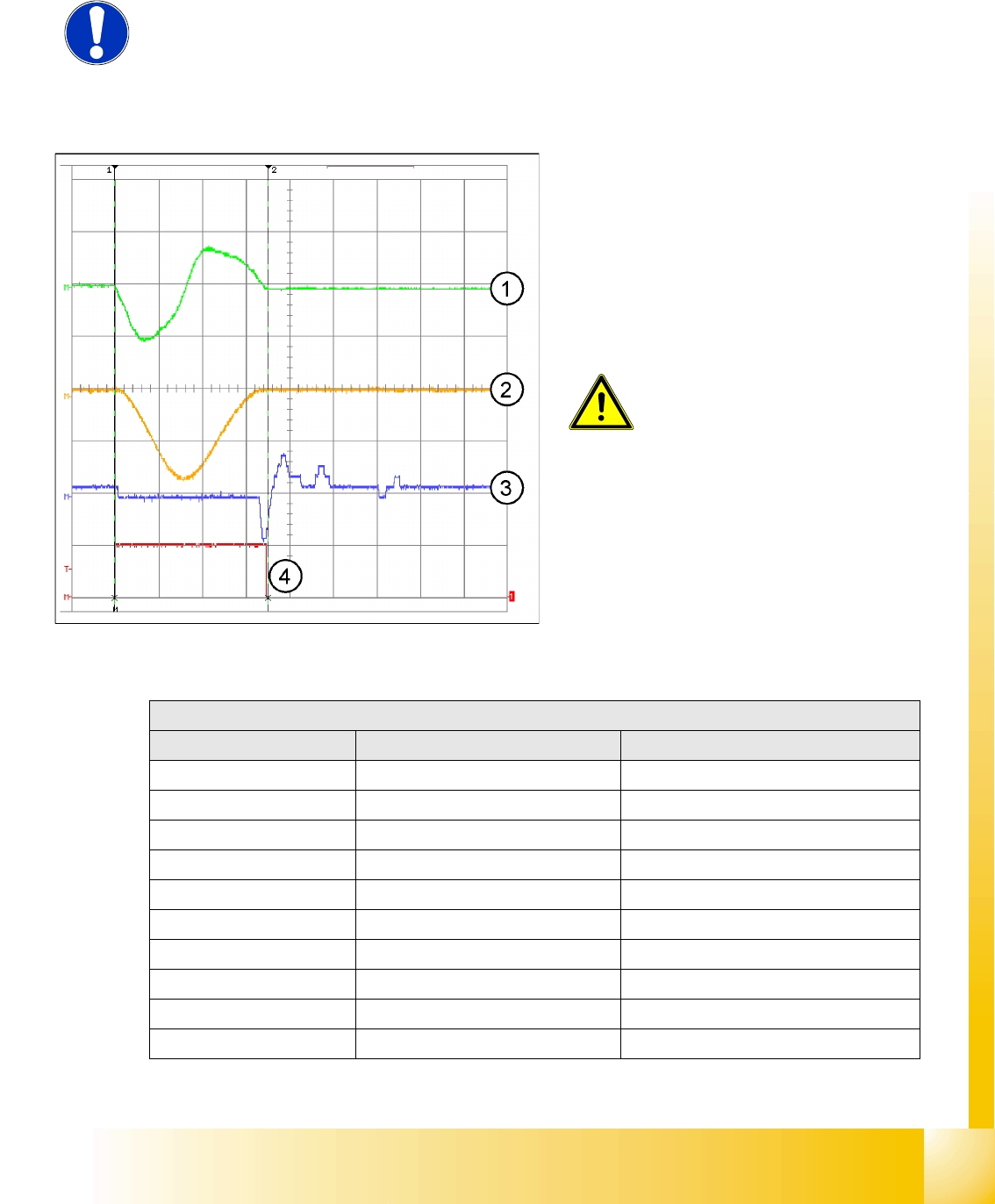
7.4.3 Check dynamic Y- axis
7.4.3.1 Test set up
7.4.3.2 Y-axis Travel Profiles for C&P12
7.4.3.3 Y-axis Travel Time Table
NOTE:
The measurement procedure is prepared and performed identically to that for
the X-axis
Legend:
1. Current signal
2. Speed – signal Vreg (Vnominal)
3. Deviation of position
4. End signal
Distance: 15mm = 15000 Digit
Time: 70 +/-5ms
ATTENTION:
The permissible position deviation for
placement with C&P12: 10 µm (digits)
Y-axis gantry axis with DLM2 (C&P12)
Distance / Digit Time / ms Tolerance /ms
500 41 +/-5
1000 43 +/-5
2000 45 +/-5
5000 55 +/-5
15000 70 +/-5
20000 75 +/-5
50000 108 +/-10
100000 143 +/-10
200000 188 +/-10
600000 370 +/-15
Axis dynamic
Axis control C&P head axes Overview Axis control Star-, Z- and DP-Axis
Student Guide SIPLACE D4 (FSE)
Axis dynamic EN 09/2006
160
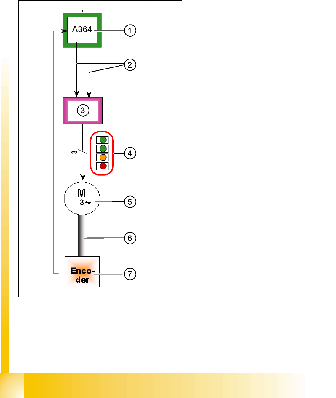
7.5 Axis control C&P head axes
7.5.1 Overview Axis control Star-, Z- and DP-Axis
The closed-circuit control system for control of the
head axes consists of the following parts. Between
the head axes, some differences which will be
explain later in this chapter.
Axis board A364
Servo board (SDS/TBS)
Motor
Measurement system (incremental scale and
encoder (read unit)
Legend:
1. Axis board A364
2. Control signals I soll "W" and I soll "U"
3. Servo amplifier
4. LED‘s on Servo board:
– Power supply ON
– Servo enable, it the enable signal from the
axis board.
– Display R.M.S. current limiter shorter than
2,5 s.
– Error: Overvoltage, overcurrent,
overtemperature or nominal current
overshoot longer than 2.5 sec.
5. 3 Phase AC motor.
6. Between the motor and the incremental
encoder exist a fixed mechanical combination.
7. Incremental encoder: transmit the exact
position of the axis The track signals are the
only feedback signals for the axes.
The servo board controls the motor directly.