00195193-02 SG D4 FSE en (1).pdf - 第174页
Axis dynamic Track signals head axes Axis control C&P head axes Student Guide SIPLACE D4 (FSE) EN 09/2006 Axis dynamic 161 7.5.1.1 Overview positioning time 12 seg ment C&P head 7.5.2 T rack signals head axes The…
Axis dynamic
Axis control C&P head axes Overview Axis control Star-, Z- and DP-Axis
Student Guide SIPLACE D4 (FSE)
Axis dynamic EN 09/2006
160
7.5 Axis control C&P head axes
7.5.1 Overview Axis control Star-, Z- and DP-Axis
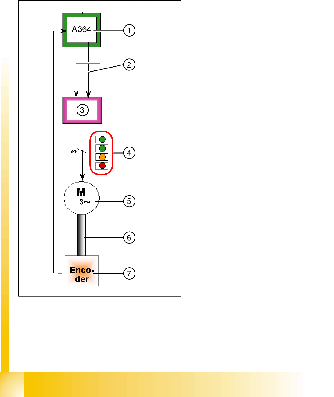
The closed-circuit control system for control of the
head axes consists of the following parts. Between
the head axes, some differences which will be
explain later in this chapter.
Axis board A364
Servo board (SDS/TBS)
Motor
Measurement system (incremental scale and
encoder (read unit)
Legend:
1. Axis board A364
2. Control signals I soll "W" and I soll "U"
3. Servo amplifier
4. LED‘s on Servo board:
– Power supply ON
– Servo enable, it the enable signal from the
axis board.
– Display R.M.S. current limiter shorter than
2,5 s.
– Error: Overvoltage, overcurrent,
overtemperature or nominal current
overshoot longer than 2.5 sec.
5. 3 Phase AC motor.
6. Between the motor and the incremental
encoder exist a fixed mechanical combination.
7. Incremental encoder: transmit the exact
position of the axis The track signals are the
only feedback signals for the axes.
The servo board controls the motor directly.

Axis dynamic
Track signals head axes Axis control C&P head axes
Student Guide SIPLACE D4 (FSE)
EN 09/2006 Axis dynamic
161
7.5.1.1 Overview positioning time 12 segment C&P head
7.5.2 Track signals head axes
The track signals play a greater role with the new drive concept for SIPLACE machines. They are
responsible for the exact and precise positioning of the axes and are used as the only response of the
closed-circuit control system so that the track signals have an important influence on dynamics of the
axes.
7.5.2.1 Communication Overview
Axis Mode/path Positioning time
Star Axis continuous run / 1 Star step 43ms +/-3ms
Z absolute, free space / 685 digits 21ms, -1ms
Z Light barrier bottom, into calibration tool pocket / approx. 685 digits 21 +/-3ms
DP 100 digits 13ms +/-3ms
DP 3600 digits 39ms +/-3ms
Positioning times for C&P12
Axes Mechanical settings Oszilloscope diagram
Star 25x: Resolution 1/1000° digital track signal amplitude 3,6Vpp
Z nothing digital track signal amplitude 3,6Vpp
DP DP read head set to 1.5 mm, parallel to the glass digital track signal amplitude 3,6Vpp
Axis dynamic
Axis control C&P head axes Track signals head axes
Student Guide SIPLACE D4 (FSE)
Axis dynamic EN 09/2006
162
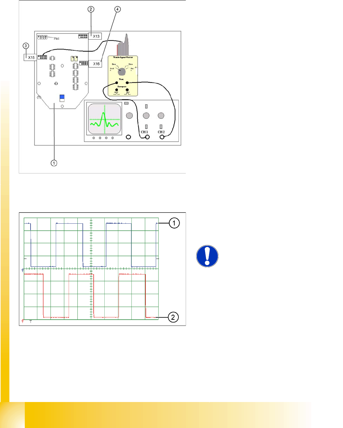
7.5.2.2 Test set up
The head axis track signals can only be measured as digital signals i.e. the analog signals are converted
into digital signals in the read unit.
Legend:
1. Intermediate distributor SP 6-12, digital
2. X13: track signal Z-axis
3. X15: track signal star axis
4. X16: track signals DP axis
Connector description of the connectors
X13, X15, X16:
1. Ground
2. Track A
3. Track A
4. Ground
5. Track B
6. Track B
7. +5V
8. Track N
9. Track N
10. Pin removed
Legend:
1. Track A
2. Track B
NOTE:
The pulse width is dependent on the
speed, the phase location is
dependent on the direction.