00195193-02 SG D4 FSE en (1).pdf - 第193页
Gantry Axis Board A364 Anticrash Function Settings Student Guide SIPLACE D4 (FSE) EN 09/2006 Gantry 179 8.2.2 Axis Board A364 Anticrash Function 8.2.2.1 Anticrash Function f or the A364 The anticrash fu nction is no lo…
Gantry
Settings Travel Ranges and Speed Monitoring at the D4
Student Guide SIPLACE D4 (FSE)
Gantry EN 09/2006
178
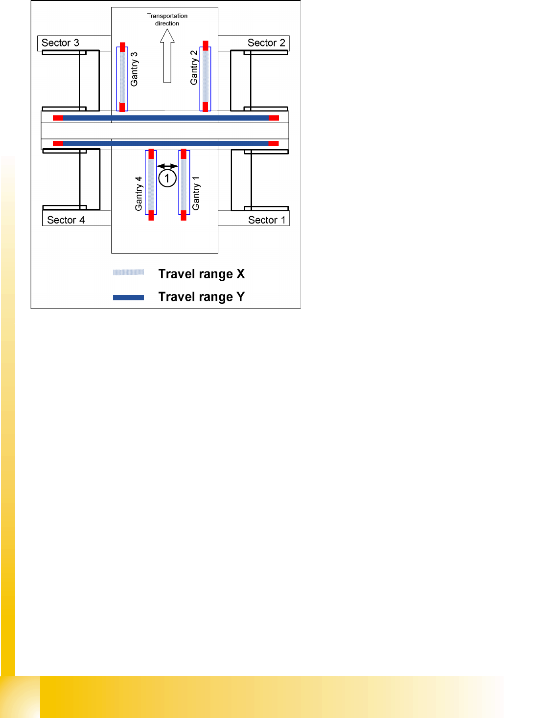
1. This means that, during travel range
calibration, the X-axis moves as far as
possible towards the minimum or maximum
position, until it touches the bumper.
The travel ranges are calculated, taking into
account the relevant safety distance.
2. In placement areas 1 and 2, gantry 1/3 moves
to the minimum position and gantry 4/2 to the
maximum position, for calculation of the Y-axis
travel range .
3. The minimum safety distance between the
gantries, during placement:minimum 4mm.

Gantry
Axis Board A364 Anticrash Function Settings
Student Guide SIPLACE D4 (FSE)
EN 09/2006 Gantry
179
8.2.2 Axis Board A364 Anticrash Function
8.2.2.1 Anticrash Function for the A364
The anticrash function is no longer provided by the anticrash board but instead by the A364 software
(application 1). This means that the proximity switches used to monitor the travel range and the
sensor for monitoring the gantry spacing are no longer required.
Tasks:
– Monitoring the travel range of the X and Y axes
Evaluation of the actual axis position in the direction of the bumper, taking the speed into
account.
– Monitoring the distance for the two Y axes in one placement area
Evaluation of the actual positions of the own and partner gantries during gantry crash monitoring.
– Counter errors for an axis
Time-based monitoring of the counter pulses received (edge control).
8.2.2.2 Anticrash Monitoring for the A364
The anticrash function is activated after the X/Y axes have been referenced. When the gantry axes are
referenced for the first time, anticrash monitoring will not be active, which is not so important, due to the
low reference speed.
After this, the bit is set for the anticrash monitoring function and the actual position for the relevant
partner gantry is continuously communicated via the SPI Bus.
The following information is exchanged between the Y axes:
Actual position of the own gantry
Status information (reference state, anticrash monitoring state ).
8.2.2.3 Error "Gantry Crash"
A “gantry crash” error is established by calculating the position difference and speed difference for both
axes. A gantry crash error is signaled via the axis board and the CAN Bus. The servo is released for both
axes and needs to be referenced again.
8.2.2.4 Count Error:
If the axis board detects a "fatal count error", the axis concerned will be released and the anticrash
function disabled. The other axis is informed of this in the status information and will also disable the
anticrash function. The released axis now needs to be referenced again,
after which the anticrash function will be re-enabled for both axes.
Gantry
Settings Axis Board A364 Anticrash Function
Student Guide SIPLACE D4 (FSE)
Gantry EN 09/2006
180
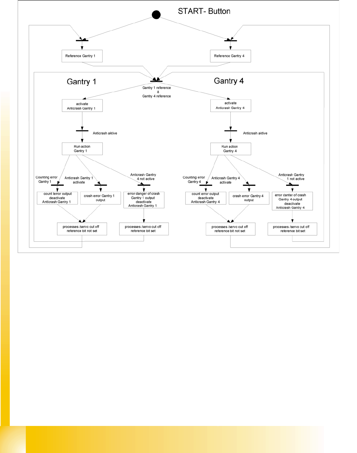
8.2.2.5 Anticrash Function - Procedure
8.2 - 1: Example of the sequence for the anticrash function in placement area 1