00195193-02 SG D4 FSE en (1).pdf - 第195页
Gantry Description of the PCB boards on the Gantry Settings Student Guide SIPLACE D4 (FSE) EN 09/2006 Gantry 181 8.2.3 Description of th e PCB boards on the Gantry The boards on the gantr y described below are basically …
Gantry
Settings Axis Board A364 Anticrash Function
Student Guide SIPLACE D4 (FSE)
Gantry EN 09/2006
180
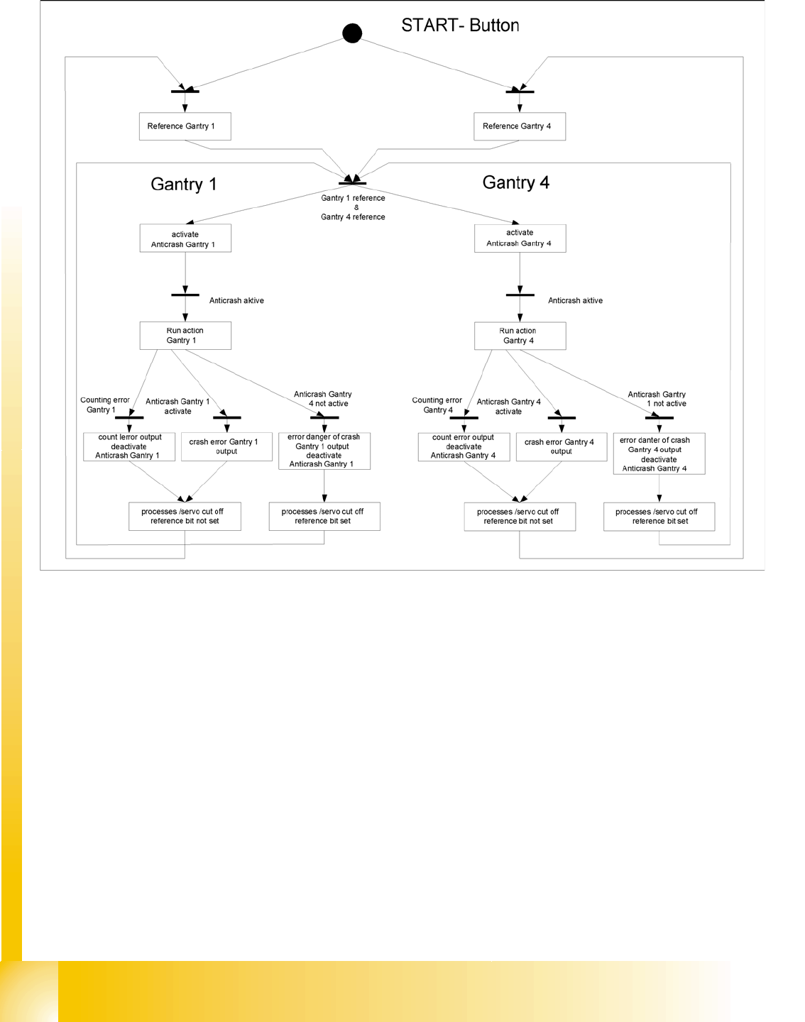
8.2.2.5 Anticrash Function - Procedure
8.2 - 1: Example of the sequence for the anticrash function in placement area 1
Gantry
Description of the PCB boards on the Gantry Settings
Student Guide SIPLACE D4 (FSE)
EN 09/2006 Gantry
181
8.2.3 Description of the PCB boards on the Gantry
The boards on the gantry described below are basically identical and do not depend on the head
configuration of D1, D2 and D4 machines. The CAN Bus terminating resistor is fixed onto the gantry head
distributor.
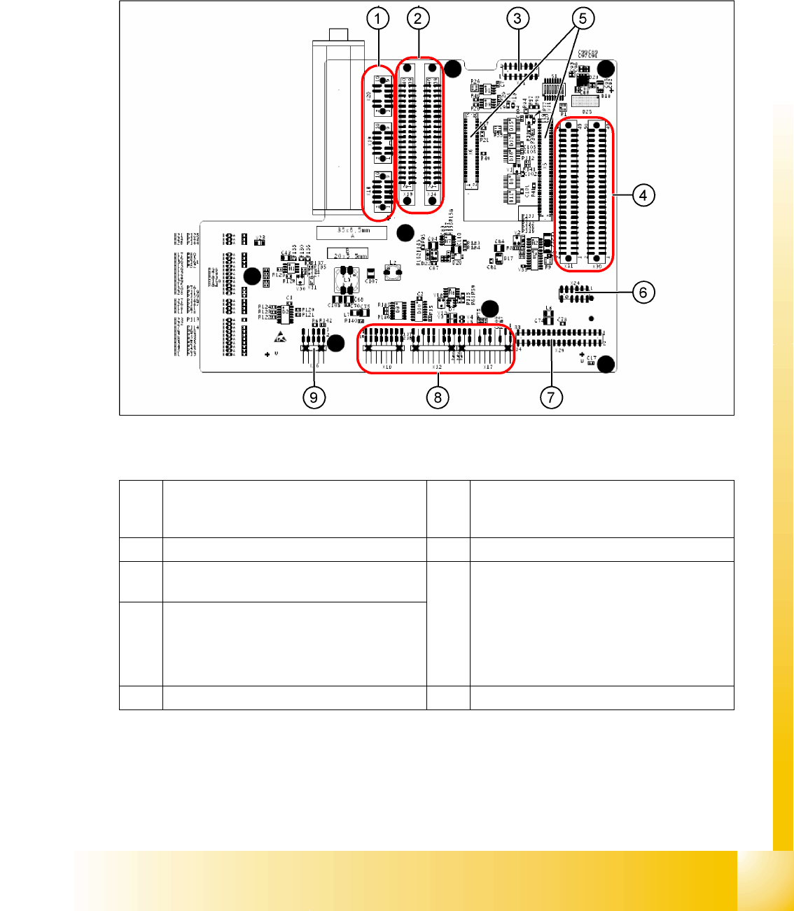
8.2.3.1 Gantry head distributor
8.2 - 2: Gantry head distributor (from above)
Legend
1 X18 stepper motor DP axis
X19 stepper motor pick up position
X20 stepper motor reject position
6 X24 Test connector for „digital track signals for
X-axis“
2 X13/X14 flat ribbon cable to C&P head 7 X29 connector for Vision board
3 X11 test connector for CAN Bus, SPI Bus,
RS232
8 X10 connector for vacuum measurement
board
X12 motor for DP axis
X16 reference proximity switch (not in use)
X17 end position proximity switch for X-axis
(not in use)
X22/X21 one wire bus (not in use)
4 X30/X31 flat ribbon cable to P&P head for D1
(D4 not in use)
5 X5/X6 connector for 16 bit processor (TQM) 9 X26 connector for CO sensor
Gantry
Settings Description of the PCB boards on the Gantry
Student Guide SIPLACE D4 (FSE)
Gantry EN 09/2006
182
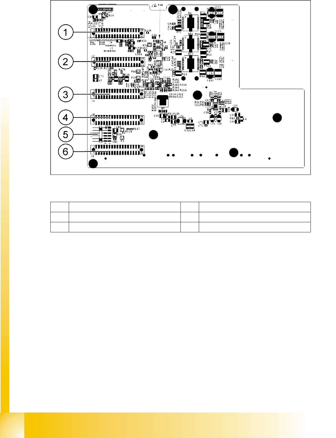
8.2 - 3: Gantry head distributor (from below)
Legend
1 X1 flat ribbon cable 4 X4 not connected
2 X2 flat ribbon cable 5 X15 connector for X-axis track signals
3 X3 flat ribbon cable 6 X9 flat ribbon cable