00195193-02 SG D4 FSE en (1).pdf - 第197页
Gantry Description of the PCB boards on the Gantry Settings Student Guide SIPLACE D4 (FSE) EN 09/2006 Gantry 183 8.2.3.1.1 Description of LEDs on the Gantry Head Distributor Legend PCB labeling LED status Description 1 1…
Gantry
Settings Description of the PCB boards on the Gantry
Student Guide SIPLACE D4 (FSE)
Gantry EN 09/2006
182
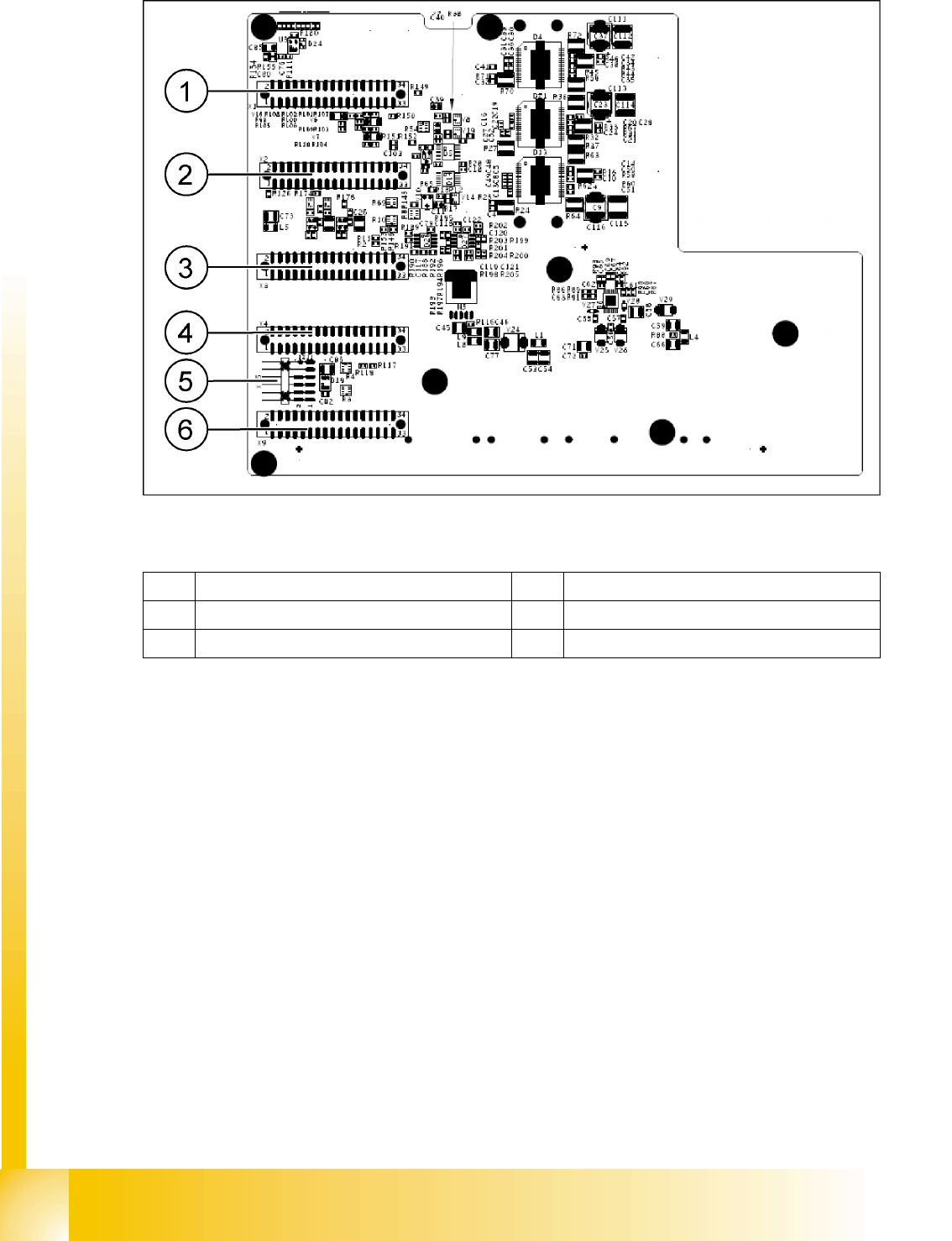
8.2 - 3: Gantry head distributor (from below)
Legend
1 X1 flat ribbon cable 4 X4 not connected
2 X2 flat ribbon cable 5 X15 connector for X-axis track signals
3 X3 flat ribbon cable 6 X9 flat ribbon cable
Gantry
Description of the PCB boards on the Gantry Settings
Student Guide SIPLACE D4 (FSE)
EN 09/2006 Gantry
183
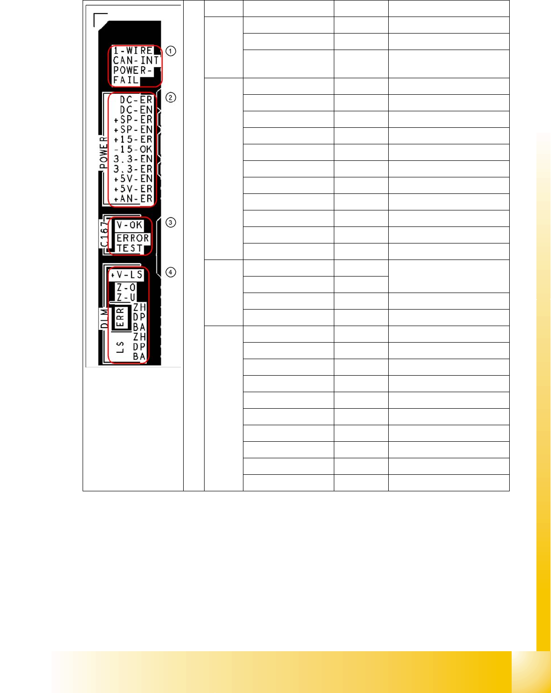
8.2.3.1.1 Description of LEDs on the Gantry Head Distributor
Legend PCB labeling LED status Description
1 1-WIRE Not in use
CAN-INT OFF not used
POWER-FAIL OFF Error +24 V power supply
(from the main machine)
2 DC-ER OFF Error DC/DC converter
DC-EN ON Enable DC/DC converter
+SP-ER OFF Error +5V track encoder
+SP-EN ON Enable +5V track encoder
+15-ER OFF Error +15V
-15-OK ON -15V is OK
3.3-EN ON Enable +3.3V digital
3.3-ER OFF Error +3.3V digital
+5V-EN ON Enable +5 V digital
+5V-ER OFF Error +5V digital
+AN-ER OFF Error analog supply C167
3 V-OK ON Internal voltage monitoring of
eSW
V-OK OFF
ERROR OFF Error eSW
TEST Toggle Timer eSW in operation
4 +V-LS ON OK + 15V light barrier
+V-LS OFF Error +15V light barrier
Z-O ON Z-axis is up
Z-U ON Z down has switched
ERR-ZH OFF Overload SM feed-in
ERR-DP OFF Overload SM rotary axis
ERR-BA OFF Overload SM reject
LS-ZH ON Light barrier SM feed-in
LS-DP ON Light barrier SM rotary axis
LS-BA ON Light barrier SM reject
Gantry
Settings Description of the PCB boards on the Gantry
Student Guide SIPLACE D4 (FSE)
Gantry EN 09/2006
184
8.2.3.2 Vision board (digital)
The Vision processor board is mounted on the gantry head distributor board. This PCB is used for all
four gantries.
8.2.3.3 CAN 16 bit Processor Board (TQ module)
The 16 BIT CAN processor is used for various different functions in the following units:
(see chapter communication and control too)
Visionboard, communication and control via the CAN Bus to the vision computer.
Gantry head distributor, control of head processes and vacuum
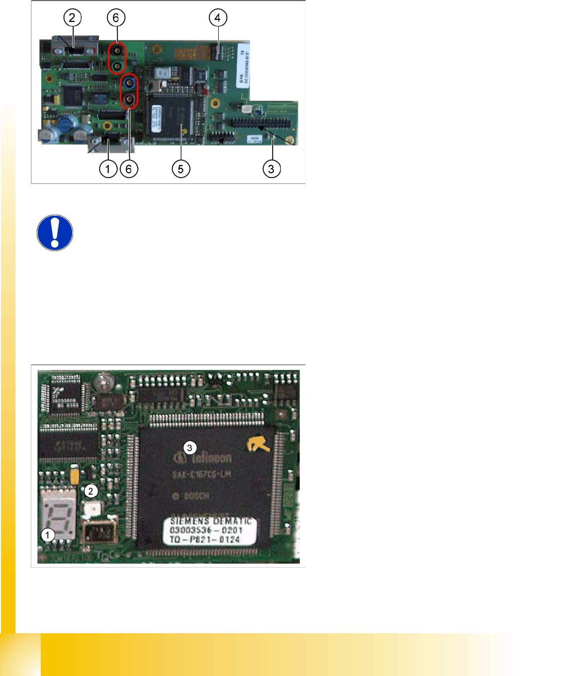
Legend:
1. X8 Connector illumination and video signals
PCB camera
2. X3 Connector illumination and video signals
component camera
3. LED‘s P15V - 15Volt / Vcc - Power supply
Vision board
4. DIP switch
5. CAN Prozessor 16 Bit (TQM Module)
6. Connector X22 - X24 Connectors for the video
cable to the trailing cable
NOTE:
The DIP switch configuration for gantry configuration is described in Section
8.2.4 Check the DIP Switches [J 184] .
Legend:
1. 7 Segment display
2. LED for manual RESET of processor
3. 16 Bit Processor