00195193-02 SG D4 FSE en (1).pdf - 第199页
Gantry Check the DIP Switches Settings Student Guide SIPLACE D4 (FSE) EN 09/2006 Gantry 185 Description of 7-segment display (norm al operation "." flashes): After switch ON the machine ap pears " 0 &quo…
Gantry
Settings Description of the PCB boards on the Gantry
Student Guide SIPLACE D4 (FSE)
Gantry EN 09/2006
184
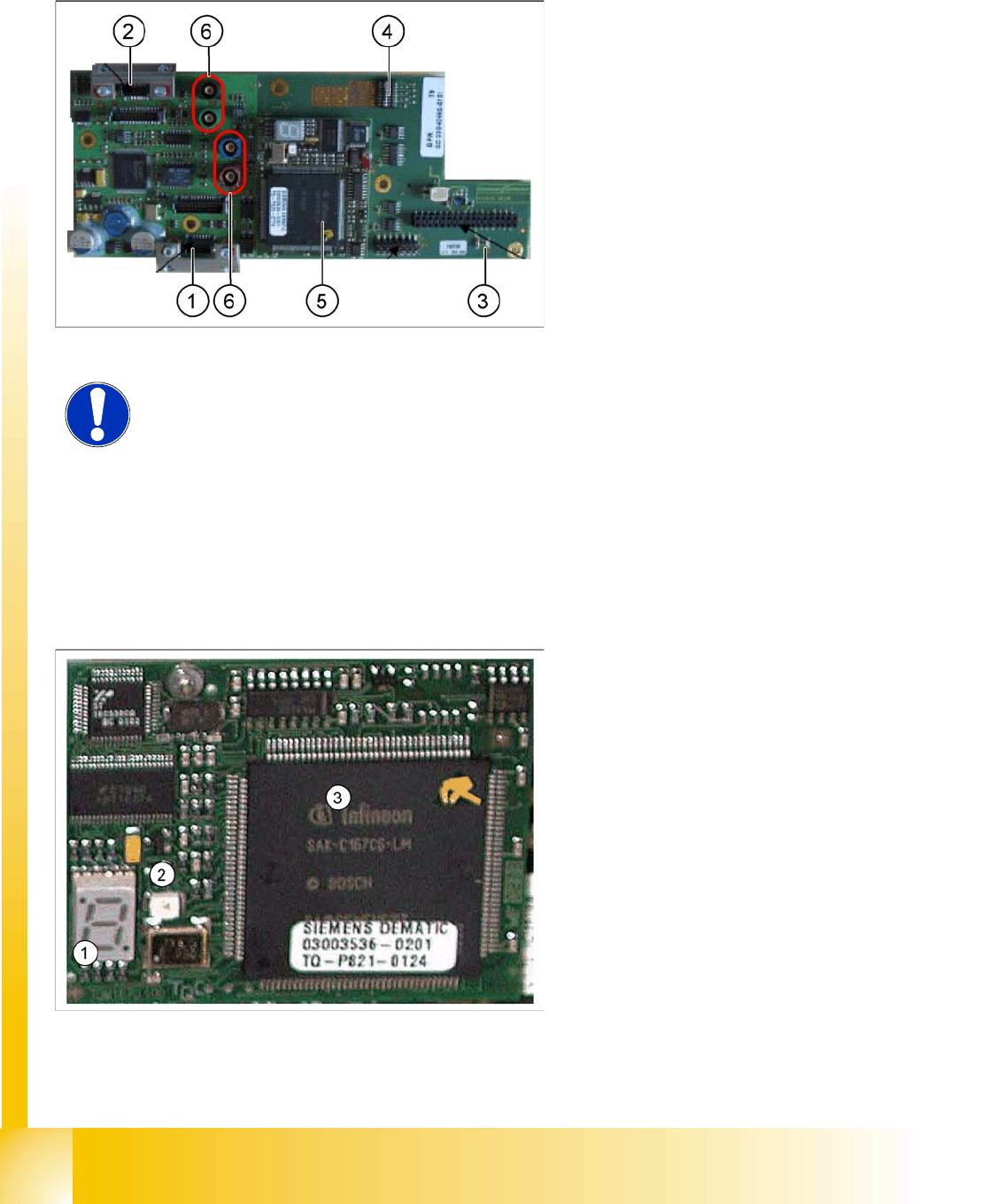
8.2.3.2 Vision board (digital)
The Vision processor board is mounted on the gantry head distributor board. This PCB is used for all
four gantries.
8.2.3.3 CAN 16 bit Processor Board (TQ module)
The 16 BIT CAN processor is used for various different functions in the following units:
(see chapter communication and control too)
Visionboard, communication and control via the CAN Bus to the vision computer.
Gantry head distributor, control of head processes and vacuum
Legend:
1. X8 Connector illumination and video signals
PCB camera
2. X3 Connector illumination and video signals
component camera
3. LED‘s P15V - 15Volt / Vcc - Power supply
Vision board
4. DIP switch
5. CAN Prozessor 16 Bit (TQM Module)
6. Connector X22 - X24 Connectors for the video
cable to the trailing cable
NOTE:
The DIP switch configuration for gantry configuration is described in Section
8.2.4 Check the DIP Switches [J 184] .
Legend:
1. 7 Segment display
2. LED for manual RESET of processor
3. 16 Bit Processor
Gantry
Check the DIP Switches Settings
Student Guide SIPLACE D4 (FSE)
EN 09/2006 Gantry
185
Description of 7-segment display (normal operation "." flashes):
After switch ON the machine appears " 0 " on the display
Display "b" --> BIOS was started.
Display flashes alternatively between "b" and "." --> no application available or unable to start
application.
Display " -I " and " I- " application was loaded.
"." flashes on the display --> ready for operation.
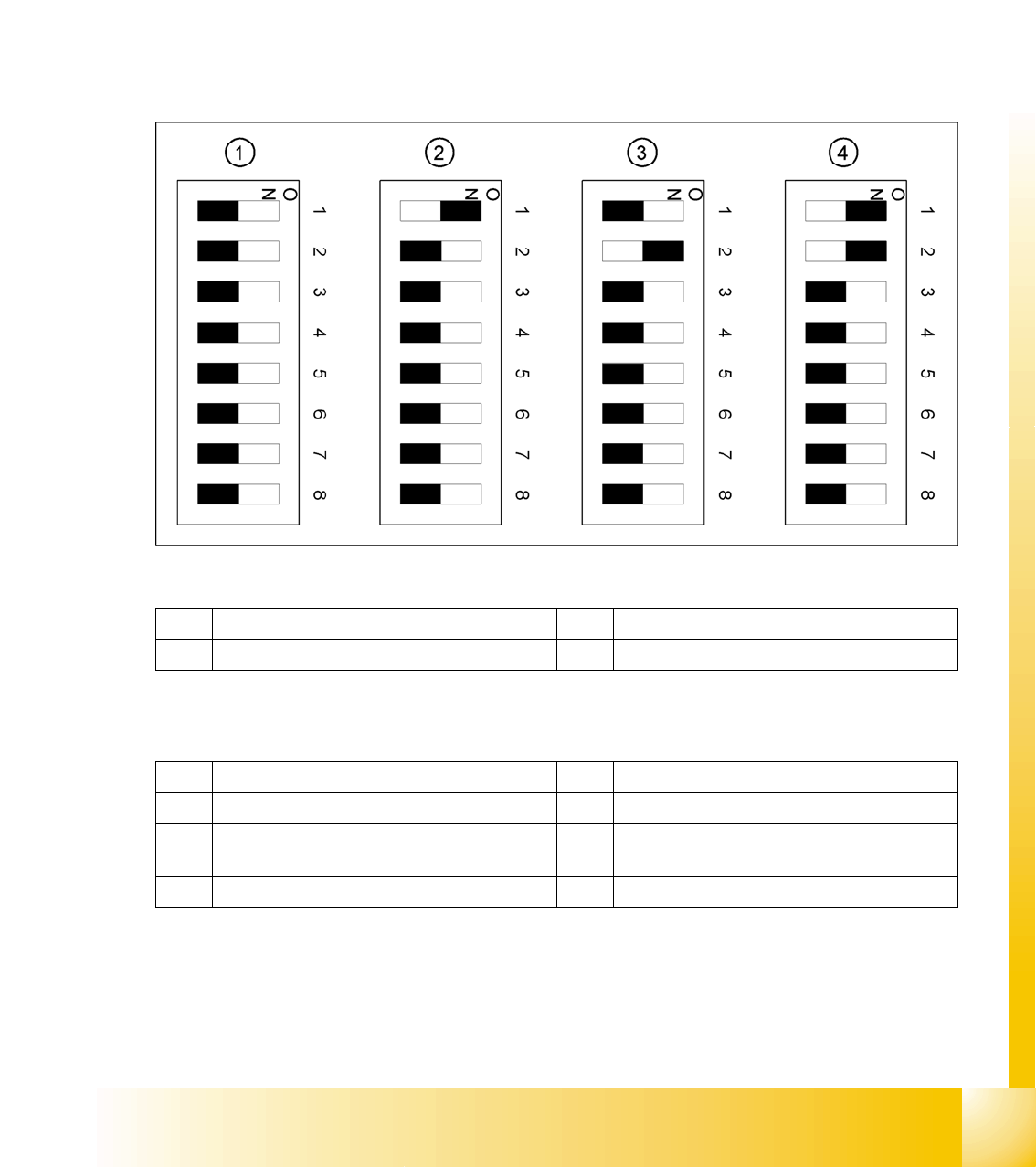
8.2.4 Check the DIP Switches
8.2.4.1 DIP Switch on Gantry Head Distributor
Legend
DIP Switch
1 Gantry 1 3 Gantry 3
2 Gantry 2 4 Gantry 4
1 P0 – gantry ID0 address switch 1 --> gantry 5 Reset - CAN processor 16 Bit (TQM module)
2 P1 – gantry ID1 address switch 2 --> gantry 6 C0 – no current function
3 S1 – switch for DLM head (delay switching on
LB down – Z-axis)
7 C1 – no current function
4 BL – Enable boot loader for serial port 8 S2 – switch for DLM head (no current function)
Gantry
Settings Mechanical adjustment of the incremental encoder
Student Guide SIPLACE D4 (FSE)
Gantry EN 09/2006
186
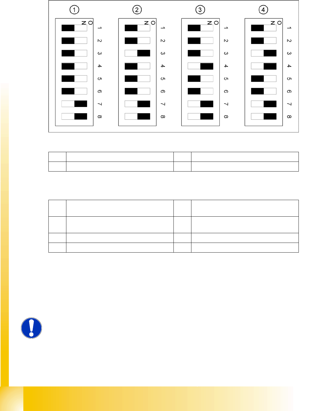
8.2.4.2 DIP switch on Vision board
Legend
DIP Switch
8.2.5 Mechanical adjustment of the incremental encoder
The incremental encoders (read units) on the X and Y axes are mechanically set to a distance of 0.4 mm
+/- 0.1 mm to the incremental scale.
After setting the incremental encoder, you need to check the zero pulse and the track signals (see Sec-
tion 7.4.1 Track signals and Zero pulse [J 149]).
1 Gantry 1 3 Gantry 3
2 Gantry 2 4 Gantry 4
1 Boot mode - CAN processor 16 Bit via
connector X11
5 WPE - Write protect enable (currently
disabled)
2 Reset - CAN processor 16 Bit to subboard 6 CAN R - switch for terminating resistance of
CAN Bus
3 P0 - Gantry address switch 1 7 Test 1 - CAN 1MBit/s ON
4 P1 - Gantry address switch 2 8 Test 0 - CAN IDs --> ON
NOTE:
To set this distance, use one or more small plastic disks with a thickness of
0.4 mm.