00195193-02 SG D4 FSE en (1).pdf - 第204页
C&P12 Placement Head Overview parts on the C&P12 Head Overview Student Guide SIPLACE D4 (FSE) EN 09/2006 C&P12 Placement Head 189 The valve p ositioning un it closes th e vacuum ch an nel to the nozzle. A sho…
C&P12 Placement Head
Overview Camera modularity at the C&P12 Head
Student Guide SIPLACE D4 (FSE)
C&P12 Placement Head EN 09/2006
188
9.1.2 Camera modularity at the C&P12 Head
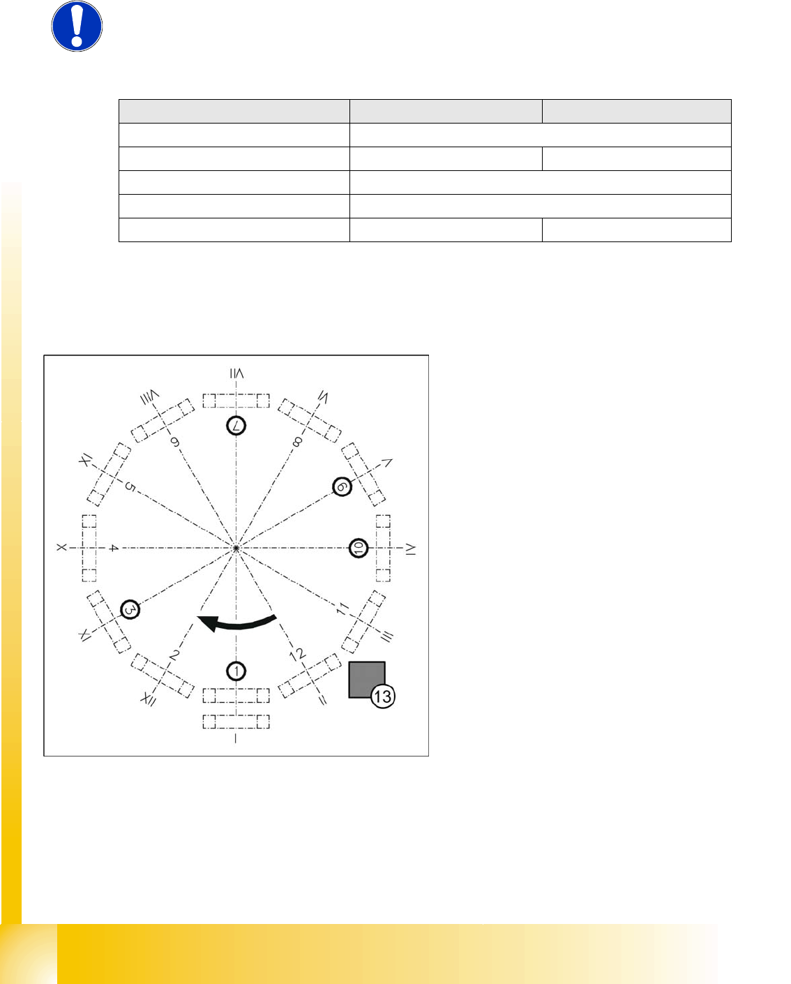
9.1.3 Position and function of the individual star stations
Star station 1
Pick-up cycle
The nozzle is lowered onto the component. Once the valve positioning unit has opened the vacuum
circuit to the nozzle, the nozzle draws up the component and removes it from the feeder module.
Placement cycle
The nozzle, together with the component, is lowered onto the PCB that has been moved into place.
NOTE:
The standard camera on the C&P12 is the 28.sst, although the CO camera
29.sst, with a higher resolution (for small 0201 components), can be installed
as an option.
Description 12 segment standard 12 segment with SST 29
CO size: Flip Chip/Bare Die 0.3mm x 0.3 mm (0201) to 18.7 mm x 18.7 mm
CO Height 0.15 mm up to 6 mm 0.15 mm up to 6 mm
Placement Accuracy +/- 80 µm for 4 (Sigma)
Angle accuracy +/- 0,7° at 4 (Sigma)
Resolution Component camera 50µm/Pixel 26µm/Pixel
Technical Data - CO Camera
Legend:
I-XII Segment numbering
1. Star station 1: pick up and place component
2. Star station 2: no function
3. Star station 3: reject component
4. Star station 4: no function
5. Star station 5: no function
6. Star station 6: no function
7. Star station 7: optically center component
8. Star station 8: no function
9. Star station 9: rotate component
10. Star station 10: position for removing and
inserting sleeves
11. Star station 11: no function
12. Star station 12: no function
13. Component sensor (optional, between star
stations 11 and 12)
C&P12 Placement Head
Overview parts on the C&P12 Head Overview
Student Guide SIPLACE D4 (FSE)
EN 09/2006 C&P12 Placement Head
189
The valve positioning unit closes the vacuum channel to the nozzle. A short air kiss of compressed
air detaches the component from the nozzle and places it on the PCB.
Star station 3
Reject cycle
After the gantry reach the X- and Y-reject position the valve positioning unit closes the vacuum
channel to the nozzle. Defective components are rejected from the nozzle with a short air kiss of
compressed air and are discarded.
Star station 7
The component is optically centered.
Star station 9
Pick-up cycle
The nozzle is rotated to the pick-up position.
Placement cycle
The component is rotated to the placement position (angle of rotation).
Star station 10
The SW move nozzles and sleeves to here for checking.
Between Star station 11&12
Option on 12 nozzle head: The presence and/or height of the component is checked before
placement.
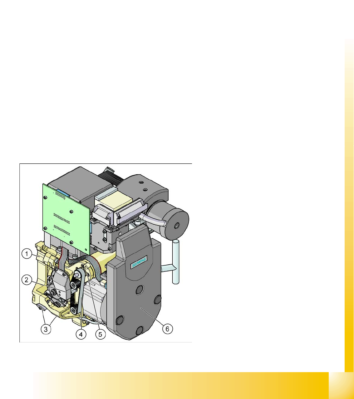
9.1.4 Overview parts on the C&P12 Head
Legend - Overview of Parts 1
1. Collect&Place head SP12 (DLM3)
(Article no. 03041228-01)
2. Light barrier "Z Axis Up " (behind the cover)
(Article no. 00347297-01)
3. Valve positioning drive, placement circuit
(Article no. 00368075-010)
Valve positioning drive, reject circuit
(Article no. 0367768-01)
4. Z-axis toothed belt
(Article no. 00334936-01)
5. Z-axis drive / DLM2
(Article no. 00341011-01)
6. SP6_12 intermediate distribution board, digital
(behind the cover)
(Article no. 00330648-05)
C&P12 Placement Head
Overview Overview parts on the C&P12 Head
Student Guide SIPLACE D4 (FSE)
C&P12 Placement Head EN 09/2006
190
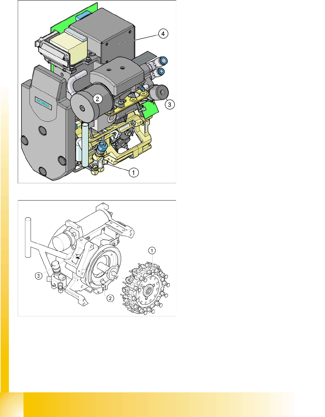
Legend - Overview of Parts 2
1. Air kiss unit / DLM2
(Article no. 00367793-01)
2. Silencer
(Article no. 03003134-01)
3. Turning station / DLM2
(Article no. 00341780-03)
4. CO camera 18x18
(Article no. 03014449-02)
CO camera 27 x 27
(Article no. 03018637-01)
Legend - Overview of Parts 3
1. Star fitted / DLM2
2. "Z-axis down" sensor
3. RSF digital encoder 12/DLM2