00195193-02 SG D4 FSE en (1).pdf - 第205页
C&P12 Placement Head Overview Overview parts on the C&P12 Head S tudent Guide SIPLACE D4 (FSE) C&P12 Placement Head EN 09/2006 190 Legend - Overview of Parts 2 1. Air kiss unit / DLM2 (Article no. 00367793-01…
C&P12 Placement Head
Overview parts on the C&P12 Head Overview
Student Guide SIPLACE D4 (FSE)
EN 09/2006 C&P12 Placement Head
189
The valve positioning unit closes the vacuum channel to the nozzle. A short air kiss of compressed
air detaches the component from the nozzle and places it on the PCB.
Star station 3
Reject cycle
After the gantry reach the X- and Y-reject position the valve positioning unit closes the vacuum
channel to the nozzle. Defective components are rejected from the nozzle with a short air kiss of
compressed air and are discarded.
Star station 7
The component is optically centered.
Star station 9
Pick-up cycle
The nozzle is rotated to the pick-up position.
Placement cycle
The component is rotated to the placement position (angle of rotation).
Star station 10
The SW move nozzles and sleeves to here for checking.
Between Star station 11&12
Option on 12 nozzle head: The presence and/or height of the component is checked before
placement.
9.1.4 Overview parts on the C&P12 Head
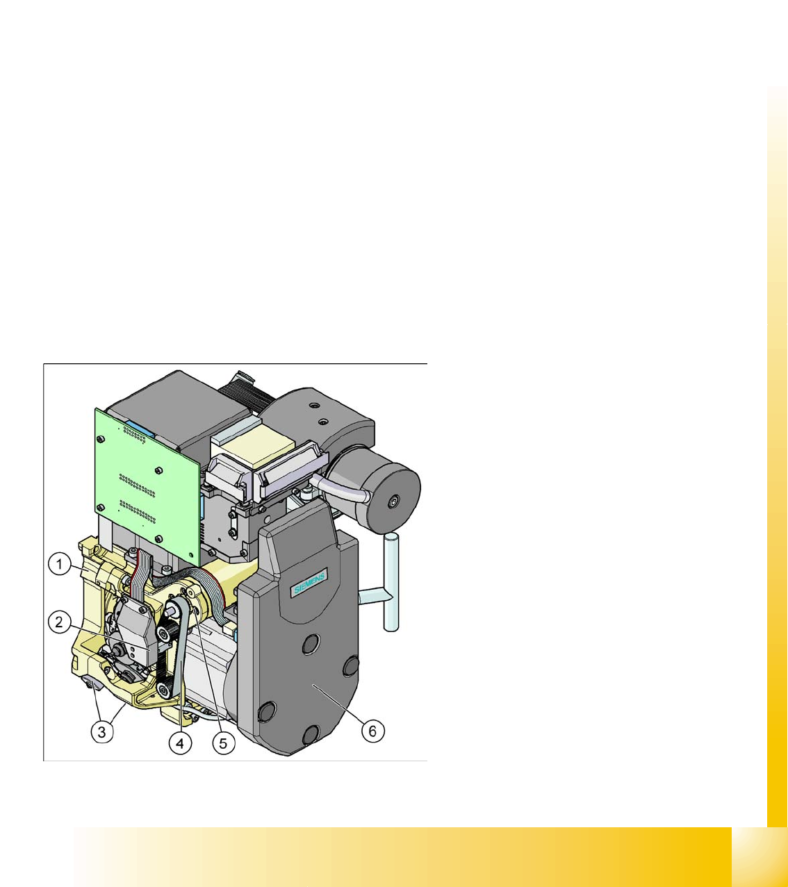
Legend - Overview of Parts 1
1. Collect&Place head SP12 (DLM3)
(Article no. 03041228-01)
2. Light barrier "Z Axis Up " (behind the cover)
(Article no. 00347297-01)
3. Valve positioning drive, placement circuit
(Article no. 00368075-010)
Valve positioning drive, reject circuit
(Article no. 0367768-01)
4. Z-axis toothed belt
(Article no. 00334936-01)
5. Z-axis drive / DLM2
(Article no. 00341011-01)
6. SP6_12 intermediate distribution board, digital
(behind the cover)
(Article no. 00330648-05)
C&P12 Placement Head
Overview Overview parts on the C&P12 Head
Student Guide SIPLACE D4 (FSE)
C&P12 Placement Head EN 09/2006
190
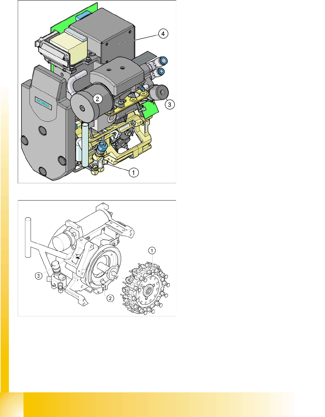
Legend - Overview of Parts 2
1. Air kiss unit / DLM2
(Article no. 00367793-01)
2. Silencer
(Article no. 03003134-01)
3. Turning station / DLM2
(Article no. 00341780-03)
4. CO camera 18x18
(Article no. 03014449-02)
CO camera 27 x 27
(Article no. 03018637-01)
Legend - Overview of Parts 3
1. Star fitted / DLM2
2. "Z-axis down" sensor
3. RSF digital encoder 12/DLM2
C&P12 Placement Head
Compressed Air Supply - C&P Head Overview
Student Guide SIPLACE D4 (FSE)
EN 09/2006 C&P12 Placement Head
191
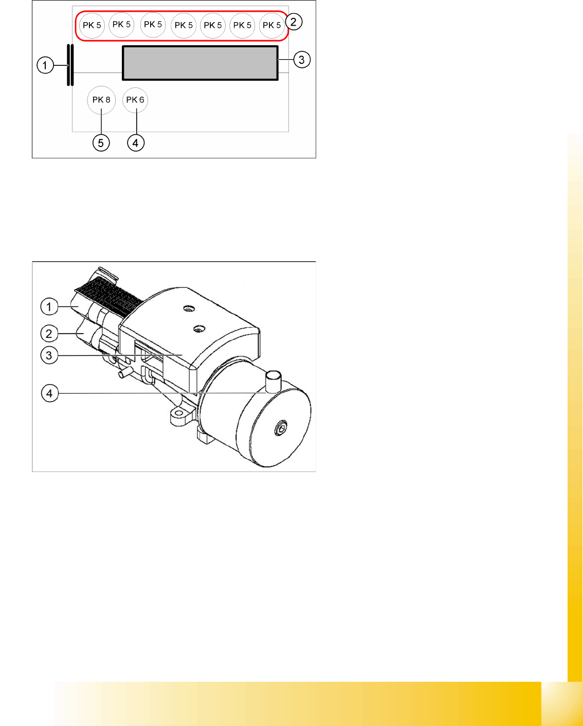
9.1.5 Compressed Air Supply - C&P Head
9.1.5.1 Vacuum generator
The placement head is supplied with 4.5 bar
compressed air from the pneumatic unit. The 7-
fold pneumatic hose is also used to cool the Y-axis
motor.
Legend:
1. Input: Discharged air Venturi nozzle
pneumatic hose (PK12)
2. Input: 7-fold pneumatic hose (PK 5)
3. Silencer for discharged air
4. Compressed air for the pickup / placement
circuit (PK6)
5. Compressed air for hold circuit (PK8)
Legend:
1. Hold circuit
2. Placement and pickup circuit for air kiss
3. Vacuum measuring board
4. Discharged air from the vacuum system to the
silencer compressed air distributor