00195193-02 SG D4 FSE en (1).pdf - 第212页
C&P12 Placement Head Checking the Nozzle Length for CO Recogn ition Placement Procedure Student Guide SIPLACE D4 (FSE) EN 09/2006 C&P12 Placement Head 197 9.2.6 Checking the Nozzle Length for CO Reco gnition 9.2.…
C&P12 Placement Head
Placement Procedure Board Recognition - Centering the Board Fiducials
Student Guide SIPLACE D4 (FSE)
C&P12 Placement Head EN 09/2006
196
9.2.4 Board Recognition - Centering the Board Fiducials
9.2.5 Preparing Nozzle 1 - Moving to Pickup Angle (0° or 90°)
The centered fiducial now defines the actual
position of the board.
The camera records an image of the 2nd
fiducial and the Vision system calculates the
center position of this image.
Another calculation determines the deviation
between the target and the calculated fiducial
position.
All board fiducials are optically centered using
this procedure.
The data is sent to the machine control
system.
Corrected values are now calculated for the
X,Y and angular position of the board.
The gantry axes now move the placement
head to the first pickup position.
NOTE: Synthetic fiducials
If synthetic fiducials are used, the procedure described above remains the
same but inkspot recognition is then performed after fiducial recognition.
The star axis rotates to 240°. Nozzle 1 is now
in the DP station.
The DP station swivels in and the DP axis
control system rotates the nozzle to its pickup
angle of 0° or 90° (default pickup angle).
As soon as the nozzle reaches its position, an
end position signal is emitted and the DP
station swivels back.
The other nozzles on the head are then moved
into their pickup angles by further rotation of the
star.
C&P12 Placement Head
Checking the Nozzle Length for CO Recognition Placement Procedure
Student Guide SIPLACE D4 (FSE)
EN 09/2006 C&P12 Placement Head
197
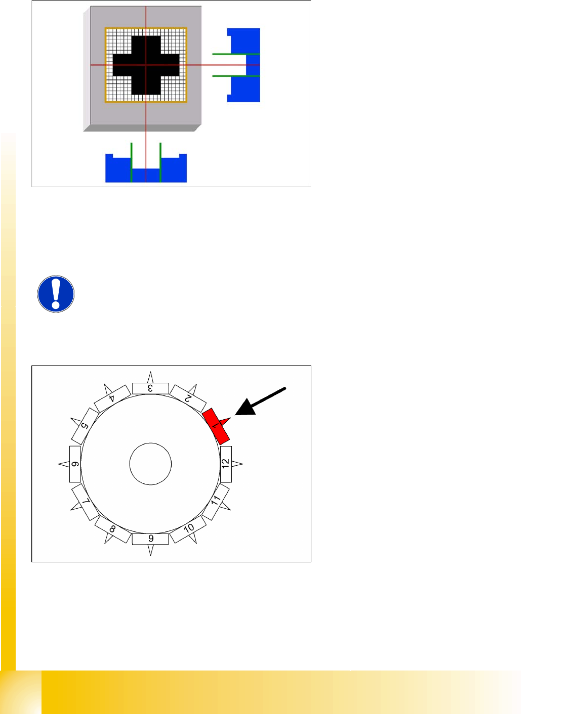
9.2.6 Checking the Nozzle Length for CO Recognition
9.2.7 Picking Up the First Component
Measurement by the CO sensor (optional) at
approx. 315°:
The CO sensor measures the length of the
nozzle. This measured length before pickup is
compared to the reference length of the
nozzle.
If a difference of -0.15 mm or +0.1 mm is
found, the gantry axes will move the
placement head into the service position for
replacement of the nozzle.
Measurement is performed "On the Fly".
Star position 0°
Vision system: no action
DP station rotation of nozzle 5 to its pickup
angle
Pickup and placement station Picking Up the
First Component
Component sensor during the next star step,
the nozzle length is measured at segment 3.
The remaining nozzles pick up components as the
star continues to rotate.
C&P12 Placement Head
Placement Procedure Picking Up Component 6
Student Guide SIPLACE D4 (FSE)
C&P12 Placement Head EN 09/2006
198
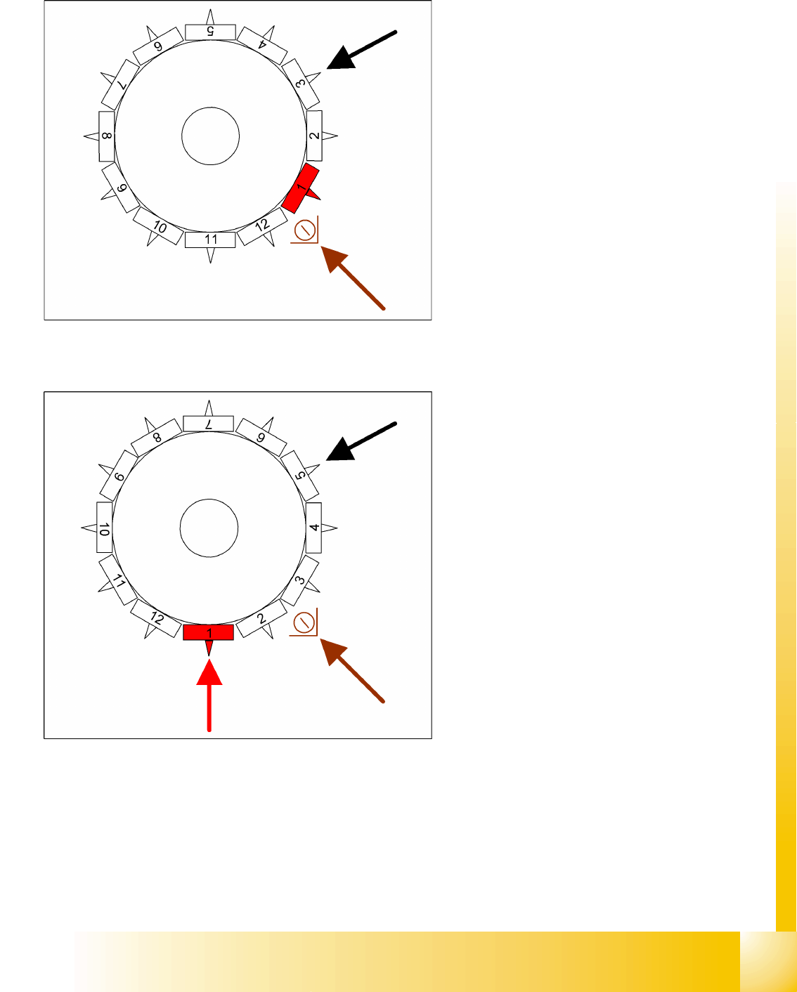
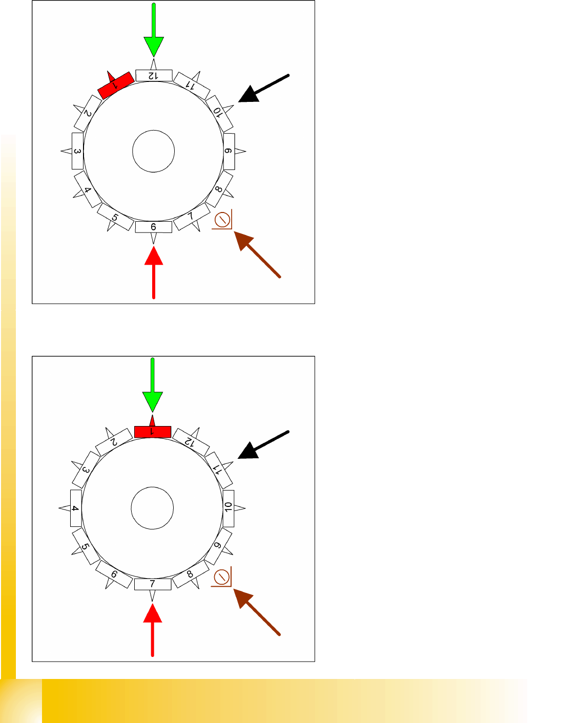
9.2.8 Picking Up Component 6
9.2.9 Picking Up Component 7
Star position 150°
Vision system: no action
DP station rotation of nozzle 10 to its pickup
angle
Pickup and placement station pick up the 6th
component
Component sensor during the next star step,
the length of nozzle 8 is measured.
Star position 180°
Vision system: component at segment 1 is
measured
DP station rotation of nozzle 11 to its pickup
angle
Pickup and placement station pick up the 7th
component
Component sensor during the next star step,
the length of nozzle 9 is measured.