00195193-02 SG D4 FSE en (1).pdf - 第216页
C&P12 Placement Head Placing Component 1 Placement Procedure Student Guide SIPLACE D4 (FSE) EN 09/2006 C&P12 Placement Head 201 9.2.14 Placing Component 1 9.2.15 Placing Component 6 Star position 0° Vision syst…
C&P12 Placement Head
Placement Procedure CO Recognition of Component at Segment 1 in the CO Sensor
Student Guide SIPLACE D4 (FSE)
C&P12 Placement Head EN 09/2006
200
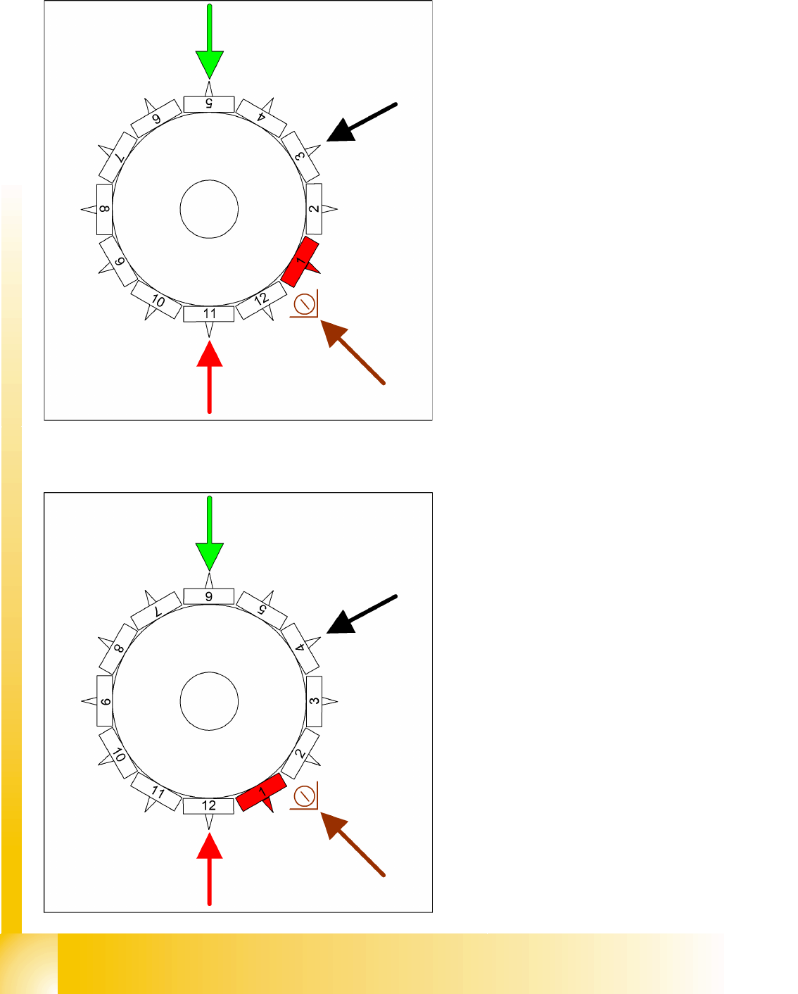
9.2.12 CO Recognition of Component at Segment 1 in the CO Sensor
9.2.13 Picking Up Component 12
Star rotates -> 330°
Measurement by the CO sensor (optional): While
the star axis rotates into position 330.000 digits:
the CO sensor checks the presence or the CO
height at segment 1.
The length measured before placement must
exceed nozzle length + CO height - CO height
tolerance.
Measurement is performed "On the Fly".
Star position 330°
Vision system: optical centering of component
6
DP station rotation of component 4 into its
exact placement angle
Pickup and placement station pick up the 12th
component
Communication with the CO table: enable the
cutter
Component sensor during the next star step,
the CO presence/CO height is checked at
segment 2.
C&P12 Placement Head
Placing Component 1 Placement Procedure
Student Guide SIPLACE D4 (FSE)
EN 09/2006 C&P12 Placement Head
201
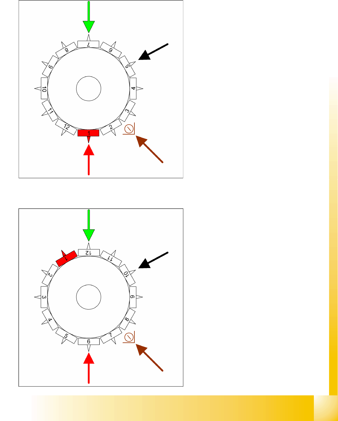
9.2.14 Placing Component 1
9.2.15 Placing Component 6
Star position 0°
Vision system: optical centering of component
7
DP station rotation of component 5 into its
exact placement angle
Pickup and placement station place
component 1
Component sensor during the next star step,
the CO presence/CO height is checked at
segment 3.
This procedure continues for the remaining
nozzles.
Star position 150°
Vision system: optical centering of component
12
DP station rotation of component 10 into its
exact placement angle
Pickup and placement station place
component 6
Component sensor during the next star step,
the CO presence/CO height is checked at
segment 8.
C&P12 Placement Head
Placement Procedure Placing Component 7
Student Guide SIPLACE D4 (FSE)
C&P12 Placement Head EN 09/2006
202
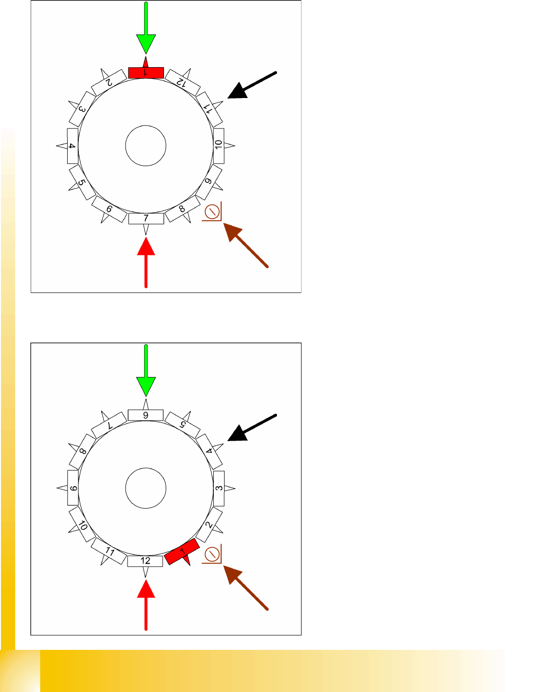
9.2.16 Placing Component 7
9.2.17 Placing Component 12
Star position 180°
Vision system: optical centering of component
1 on other gantry
DP station rotation of component 11 into its
exact placement angle
Pickup and placement station place
component 7
Component sensor option: during the next star
step, the CO presence/CO height is checked
at segment 9.
Star position 330°
Vision system: optical centering of component
6 on other gantry
DP station rotation of nozzle 4 into the pickup
angle for the next placement cycle.
Pickup and placement station place
component 12
Component sensor option: during the next star
step, the nozzle length is measured at
segment 2.