00195193-02 SG D4 FSE en (1).pdf - 第219页
C&P12 Placement Head Placement Procedure Detailed Rotation of DP Station 1. Swivel In S tudent Guide SIPLACE D4 (FSE) C&P12 Placement Head EN 09/2006 204 9.2.21 Detailed Rot ation of DP St ation 1. Swivel In 9.2.…

C&P12 Placement Head
Pickup and Placement Cycle For the Next Components Placement Procedure
Student Guide SIPLACE D4 (FSE)
EN 09/2006 C&P12 Placement Head
203
9.2.18 Pickup and Placement Cycle For the Next Components
After all components in the first head cycle have been placed on the board, the gantry axes move
the placement head to the pickup position for the next pickup cycle.
The next pickup cycle is performed for components 13 - 24.
The subsequent pickup cycles are then performed in the same manner. The machine performs
repair runs where necessary.
9.2.19 Segment with a "Defective Component“
If the optical centering of a component (ident error) or the vacuum check before placement (alternatively,
CO recognition before placement) fails, the component will not be placed and will remain on the nozzle.
The turning station will still rotate this nozzle into the pickup angle for the new component , if this
segment is in the rotation position.
If this segment is in the pickup position:
the release procedure will be enabled,
the X/Y axes will move to the reject position for this gantry,
the star will rotate the segment into the reject position,
the component will be released downwards with air kiss
and the new component will be taken up.
The rejected component will then be placed in a repair run after all the other placement cycles for this
placement head have been performed.
9.2.20 Finishing Board Placement
The SIPLACE placement station enables the conveyor system and moves the board to the output
conveyor.
Finally, the SIPLACE placement station reports the number of components used (placed and
rejected) to the line computer.
The OIS (Operator Information System) compiles the placement statistics in relation to the
programmed settings, the programmed utilization and the last reset time. This detailed data is used
to optimize the process.
The machine is now ready for the next board.
C&P12 Placement Head
Placement Procedure Detailed Rotation of DP Station 1. Swivel In
Student Guide SIPLACE D4 (FSE)
C&P12 Placement Head EN 09/2006
204
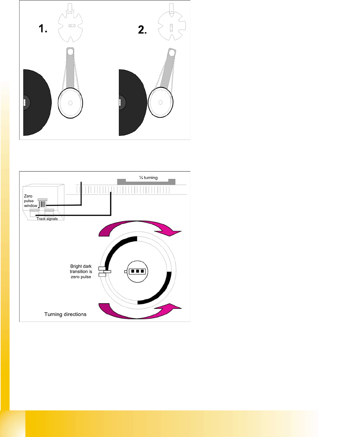
9.2.21 Detailed Rotation of DP Station 1. Swivel In
9.2.22 Positioning into Pickup Angle
Diagram 1 shows the initial position (state after
reference run).
From the initial position, the stepping motor
rotates by 90° for swivel-in.
The DP station swivels in and contacts the
sleeve (incremental disk).
The stepping motor is monitored by the light
barrier on the cam disk.
Diagram 2 shows the status after swiveling in.
This is the start command for the DP axis
drive.
The DP axis positions the segment to the
relevant zero pulse and checks the signal level
at a distance of 3 digits.
An end position signal is emitted if the actual
position deviation is within the permitted
tolerance.
There is no difference between the 0° and
180° or 90° and
90° pickup angles.
C&P12 Placement Head
Positioning into Placement Angle Placement Procedure
Student Guide SIPLACE D4 (FSE)
EN 09/2006 C&P12 Placement Head
205
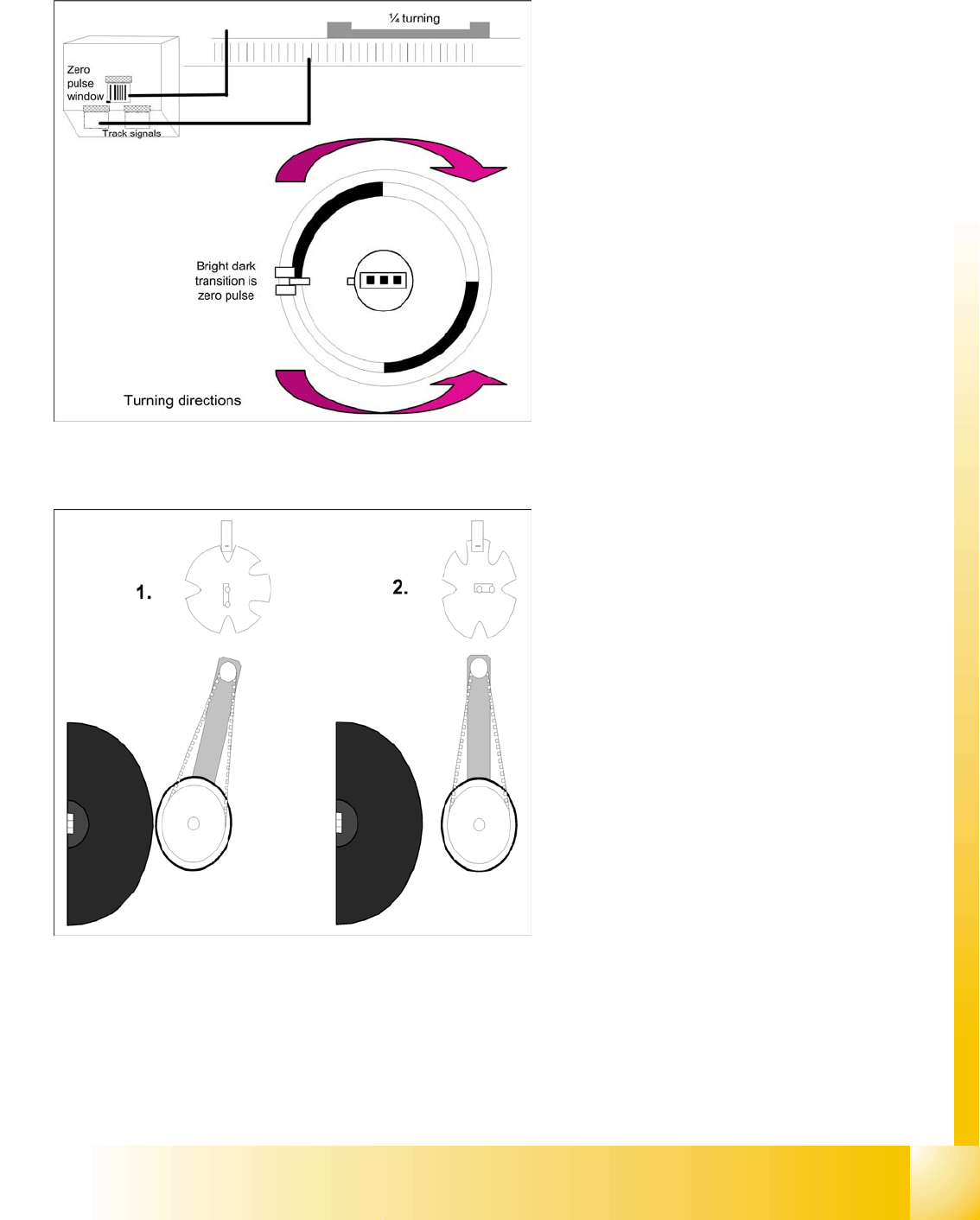
9.2.23 Positioning into Placement Angle
9.2.24 Detailed rotation of DP station, 3. Swivel Out
When positioning begins, the actual position of
the axis is set to 0 by setting the position
counter of the DP axis to 0.
The DP drive is operated in relative positioning
mode.
The DP axis starts to move towards the target
position which is calculated from the station
calibration values, the line computer
programming values and the centering values
of the placement procedure.
An end position signal is emitted as soon as
the actual position deviation is within the
permitted tolerance.
The command to start swiveling out is the end
position signal from DP positioning.
The DP drive is still located at the sleeve.
Diagram 1 shows the status when swiveled in.
The stepping motor is controlled by the light
barrier on the cam disk.
From its swiveled-in status, the stepping motor
rotates by 90° in a counterclockwise direction,
to swivel out.
Diagram 2 shows the status when swiveled
out.