00195193-02 SG D4 FSE en (1).pdf - 第232页
C&P12 Placement Head Z-Axis Up Travel Profiles - Placement Student Guide SIPLACE D4 (FSE) EN 09/2006 C&P12 Placement Head 217 9.4.2 Z-Axis Up 9.4.2.1 S t andard Mode - Placement: Z-Axis Up LB down switches: End…
C&P12 Placement Head
Travel Profiles - Placement Z-Axis Down
Student Guide SIPLACE D4 (FSE)
C&P12 Placement Head EN 09/2006
216
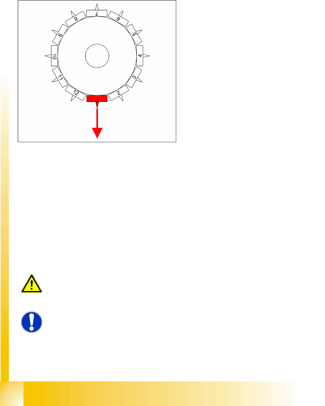
9.4.1.4 Detailed Placement Procedure: Z-Axis Downwards with Waiting Time at Placement
Benefits of Special Mode "Waiting Time - Placement"
With the "waiting time - placement" option you can:
Combine any of the Z-axis operating modes.
With this "waiting time - placement" option you can:
Press the BARE-DIE CO into the adhesive with placement force, so that the adhesive flows under
the CO surface and sticks over the surface.
Very big COs can be pressed into the soldering paste so that all leads contact with the paste.
End position signal for X/Y and star axes:
All 3 end position signals available
Perform vacuum test "before placement", to
determine whether the CO is at the nozzle.
Z-axis starts:
Positioning of Z-axis downwards
LB up switches:
Electromagnetic valve for air kiss ON
Release signal for function LB down
LB down switches:
End position signal for positioning Z-axis
down;
And valve adjusting drive pickup/placement
position ON for air kiss
Special mode "Waiting time down"
The end position signal Z-axis down starts the
waiting period timer in the MC.
After the waiting period, the air kiss pressure is
measured.
Positioning upwards begins.
ATTENTION:
During the "waiting period down", the Z-axis remains on the CO, even if
emergency STOP is pressed or the protective hood is opened!
NOTE:
The same programming option is available for the pickup procedure. However,
due to the waiting period, this option makes the placement procedure longer
than the standard placement procedure!
C&P12 Placement Head
Z-Axis Up Travel Profiles - Placement
Student Guide SIPLACE D4 (FSE)
EN 09/2006 C&P12 Placement Head
217
9.4.2 Z-Axis Up
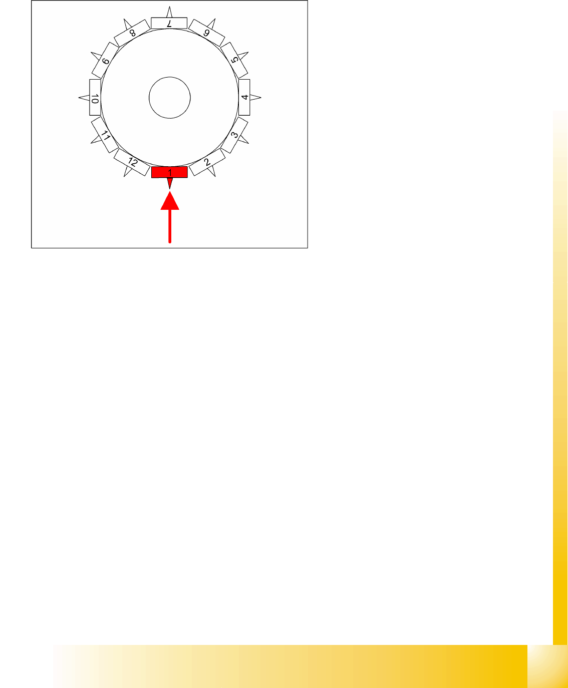
9.4.2.1 Standard Mode - Placement: Z-Axis Up
LB down switches:
End position signal for downwards and valve
positioning drive "ON" for air kiss
Measurement of air kiss pressure during
placement
Start signal for upwards movement
Z-axis starts:
Positioning of Z-axis upwards
LB up switches:
Electromagnetic valve for air kiss OFF
Reset LB down signal
Start signal for gantry axes
Z-axis end position signal (Z-axis at 0 position):
Enables vacuum query: "Segment airtight"
after placement (SR/MC503)
Start signal for star axis
C&P12 Placement Head
Travel Profiles - Placement Z-Axis Up
Student Guide SIPLACE D4 (FSE)
C&P12 Placement Head EN 09/2006
218
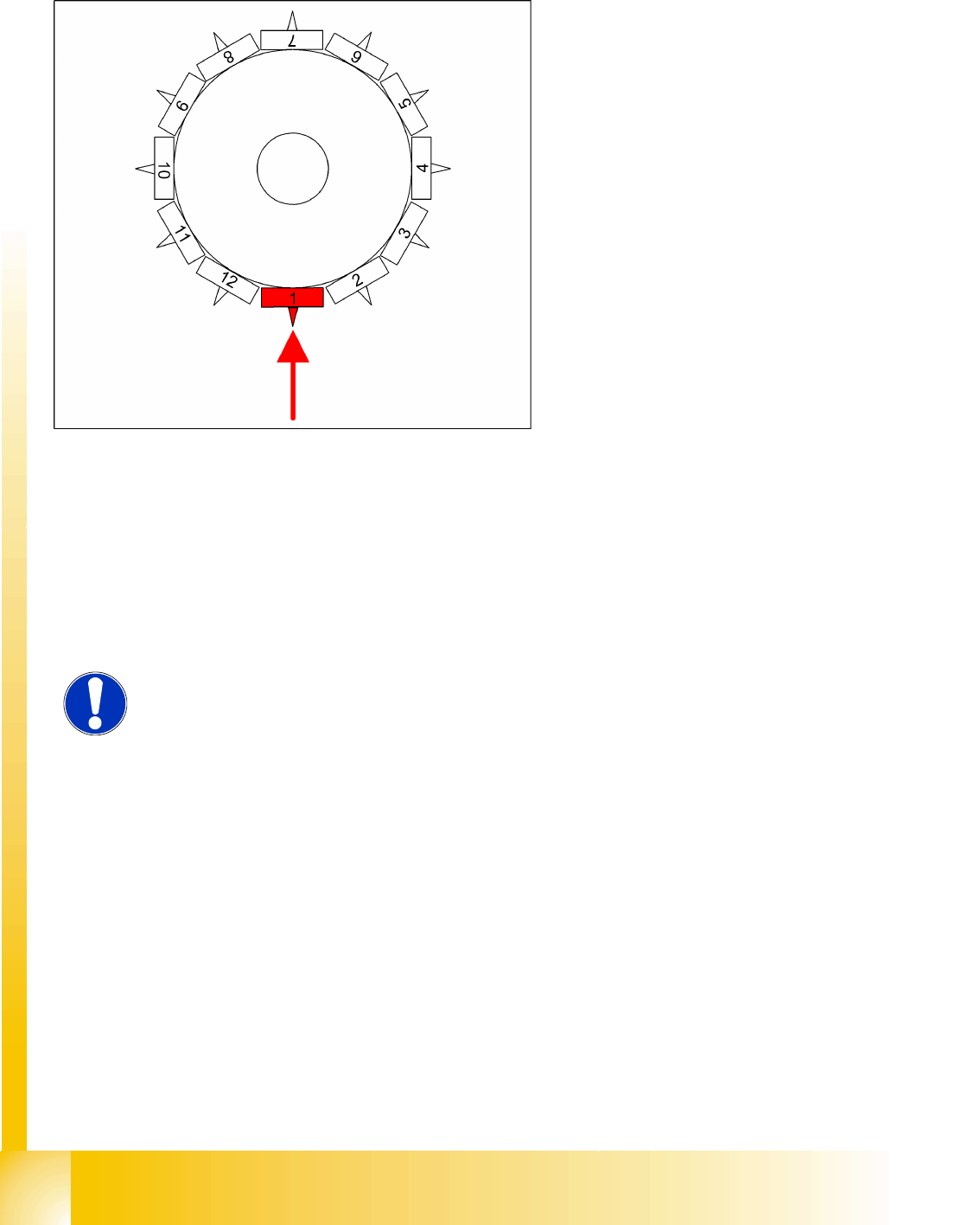
9.4.2.2 Placement: Z-Axis Upwards with "Slow Start"
Benefits of Special Mode "Slow Start"
The CO stays on the board even if the soldering paste has a low holding force.
From LRU/LRL 503 and SIPLACE Pro, this
placement type can "only" be programmed in the
CS "for SR/MC 503 stations and higher".
LB down switches:
End position signal for downwards and valve
positioning drive ON for air kiss
Measurement of air kiss pressure during
placement
Start signal for upwards movement
Z-axis starts:
Positioning Z-axis up with reduced starting
speed for the first 44 digits
LB up switches:
Electromagnetic valve for air kiss OFF
Reset LB down signal
Start signal for gantry axes
Z-axis end position signal (Z-axis at 0 position):
Enables vacuum query: "segment airtight?"
after placement (SR/MC503)
Start signal for star axis
NOTE:
However, this option makes the placement procedure around 20 ms longer than
the standard placement procedure.