00195193-02 SG D4 FSE en (1).pdf - 第238页
C&P12 Placement Head Setting the resolution on the star axis Set tings Student Guide SIPLACE D4 (FSE) EN 09/2006 C&P12 Placement Head 223 9.5.3 Setting the resolu tion o n the st ar axis 9.5.4 Setup of the Digita…

C&P12 Placement Head
Settings Overview of Settings for C&P12 (DLM3)
Student Guide SIPLACE D4 (FSE)
C&P12 Placement Head EN 09/2006
222
9.5.2 Overview of Settings for C&P12 (DLM3)
X13, 10-pole Test connection for the Z-axis track signals
X14, 10-pole not used
X15, 10-pole Test connection for the Star-axis track signals
X16, 10-pole Test connection for the Dp-axis track signals
Connectors Description
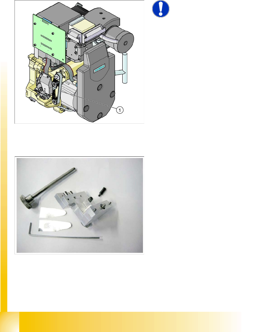
Description Tools &Equipment Adjustments
Mounting the star onto the motor
shaft of the star motor
Adjustment with the power pack and
the gauge for the star
Check the magnetic neutral position
in SITEST.
(max. deviation 95 digits)
Determine zero point correction for
the star
Gauge for zero point correction /
Sitest
Determine zero point correction
value in SITEST
--> enter positions.
Switch position on DLM3 (resolution
of track signals 10 - 25)
nothing HF/X/D machines at switch position
25
DP-axis Incremental encoder
adjustment to the glass scale
(segment)
Parallel pin 1,4 - 1,6 mm Distance 1,5 mm
Adjustment mechanical position of
valve drives
Distance gauge 0.2 mm 0.2 mm distance plunger to the valve
frame
Light barrier bottom position Z-axis Parallel pin 1,0 mm Distance 1,0 mm
Clamping device on Z-belt Tension jack must lie on the belt
teeth at the top and bottom.
Belt tension of the Z-axis Belt tension measurement device Belt tension 280 +/- 5 Hz
Setting the stop for the Z-axis Gauge for the Z-mechanical end
stop (03019865-01)
Correct position are necessary to
determine the zero point correction
Z-axis.
Mechanical adjustments Air kiss
tubes on the star
Check with your eyes Check the distance between
incremental encoder dp and air kiss
tubes.
Adjustments tube for air kiss supply feeler gauge Air kiss tubes should be approx. 0,7
mm over the frame of the circular
guide
Adjustments air pressure values Compressed air testing device 150 mbar on open 9x4 nozzle
C&P12 Placement Head
Setting the resolution on the star axis Settings
Student Guide SIPLACE D4 (FSE)
EN 09/2006 C&P12 Placement Head
223
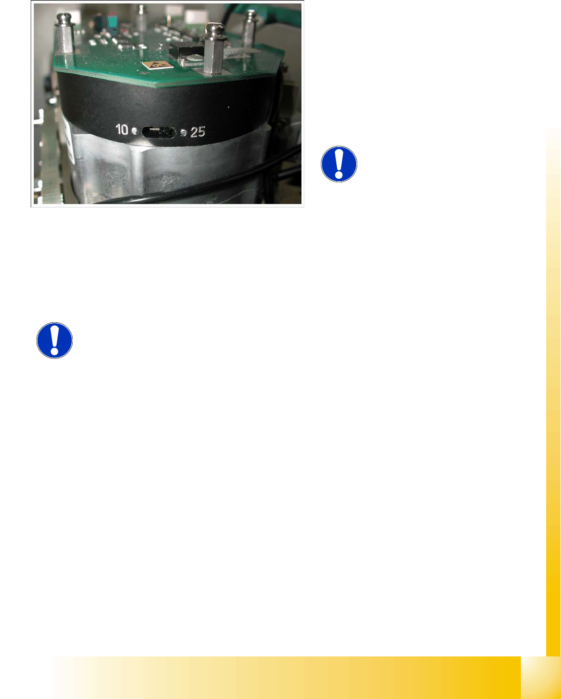
9.5.3 Setting the resolution on the star axis
9.5.4 Setup of the Digital Rotary Transducer of the DP - Axis
Remove sleeve 1 and insert the Star zero point gauge, in order to mechanically fix the Star.
Now, remove sleeve 4 or the sleeve 2 for the 6 segment C&P head as well and align the transducer.
With the help of a parallel pin, set the rotary transducer of the DP - axis to 1.5 mm, parallel to the
glass pane of the segments.
Legend:
1. The switch for the star axis resolution is
directly beneath the C&P head on the star
motor.
X Check the setting of this switch (1).
HS-60 and S-27 HM: Switch position 10
D, HF/HF3 and X machines: Switch position
25
NOTE:
Only setting the switch, if the machine
power is off.
NOTE:
Make sure that a 1.4 mm test probe can be easily passed through and that a
probe with 1.6 mm can not be passed through.
C&P12 Placement Head
Settings Belt tension Z-axis
Student Guide SIPLACE D4 (FSE)
C&P12 Placement Head EN 09/2006
224
9.5.5 Belt tension Z-axis
9.5.6 Setting the Z-Axis Upper Stop
9.5.6.1 Tools and Devices
9.5.6.2 General
From software version 602.01 onwards, during the reference run, the Z-axis moves into the star position
with +/-6250/6750 digits downwards or up into the crank, to determine the Z-axis zero point correction
factor. The prerequisite for this is the correct setting of the upper end position stop of the Z-axis. This
ensures that the Z.axis is in the center of the raceway and that the z-axis zero point can be correctly
determined.
NOTE:
The measurement point on the
measurement head should be in the
middle, between two deflection
pulleys.
The measurement head should be
kept at a distance of maximum 2 -
3 mm from the toothed belt.
Legend:
1. Measurement point for the belt tension
X Attach the measuring head in front of the
toothed belt (1) .
X Strike the toothed belt, to reach a stimulation
of vibration of the open ended toothed belt.
X If the belt tension frequency does not match
the value 280 Hz ±10 Hz, tension or relax the
belt via the drive motor fastening.
X Repeat these instructions until the belt tension
is correct.
Set of DIN 911 Allen keys
Gauge for Z-limit stop, article no. 03019865-01